
Split conveniently-folded core rod structure applied to injection mold

An injection mold and split technology, which is applied in the field of split mandrel structure, can solve problems such as lack of material or trachoma, affect product quality, uneven solution flow, etc., and achieve the effect of improving the functional structure

Active Publication Date: 2020-03-17
XIAMEN HUAYE PRECISE MOLD CO LTD
View PDF4 Cites 0 Cited by
  • Summary
  • Abstract
  • Description
  • Claims
  • Application Information

AI Technical Summary

Problems solved by technology

[0005] The purpose of the present invention is to provide a split and foldable mandrel structure applied to injection molds, so as to solve the problem that the existing mandrel similar to the above-mentioned structure proposed in the background technology is used. Although the part will be reheated by the internally designed heating mechanism to improve the fluidity of the solution, when the stepped shaft products we mentioned above are blown, it will still be due to the fluidity of the solution at the shoulder. After the product is formed by instability, there will be material shortage or trachoma in these parts, which will affect the quality of the product. This is mainly caused by the uneven flow of the solution, and after the upper and lower cover cavities are combined to form the product, it is difficult to realize the problem of upper and lower separation.

Method used


Image

  • Split conveniently-folded core rod structure applied to injection mold
  • Split conveniently-folded core rod structure applied to injection mold
  • Split conveniently-folded core rod structure applied to injection mold

Examples


Embodiment Construction

[0025] The following will clearly and completely describe the technical solutions in the embodiments of the present invention with reference to the accompanying drawings in the embodiments of the present invention. Obviously, the described embodiments are only some, not all, embodiments of the present invention.

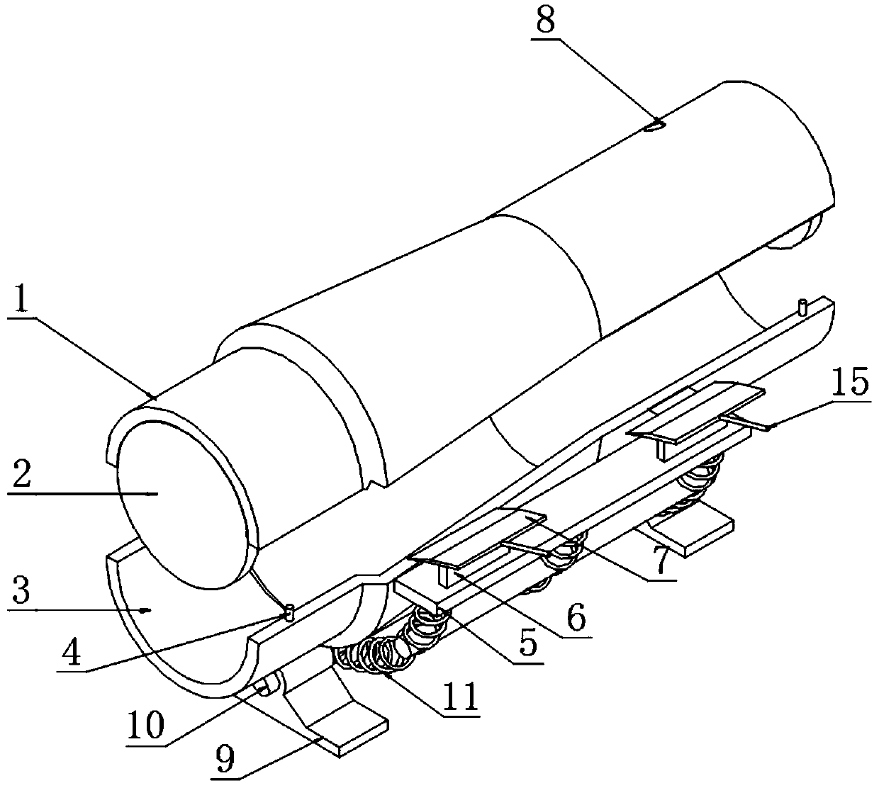
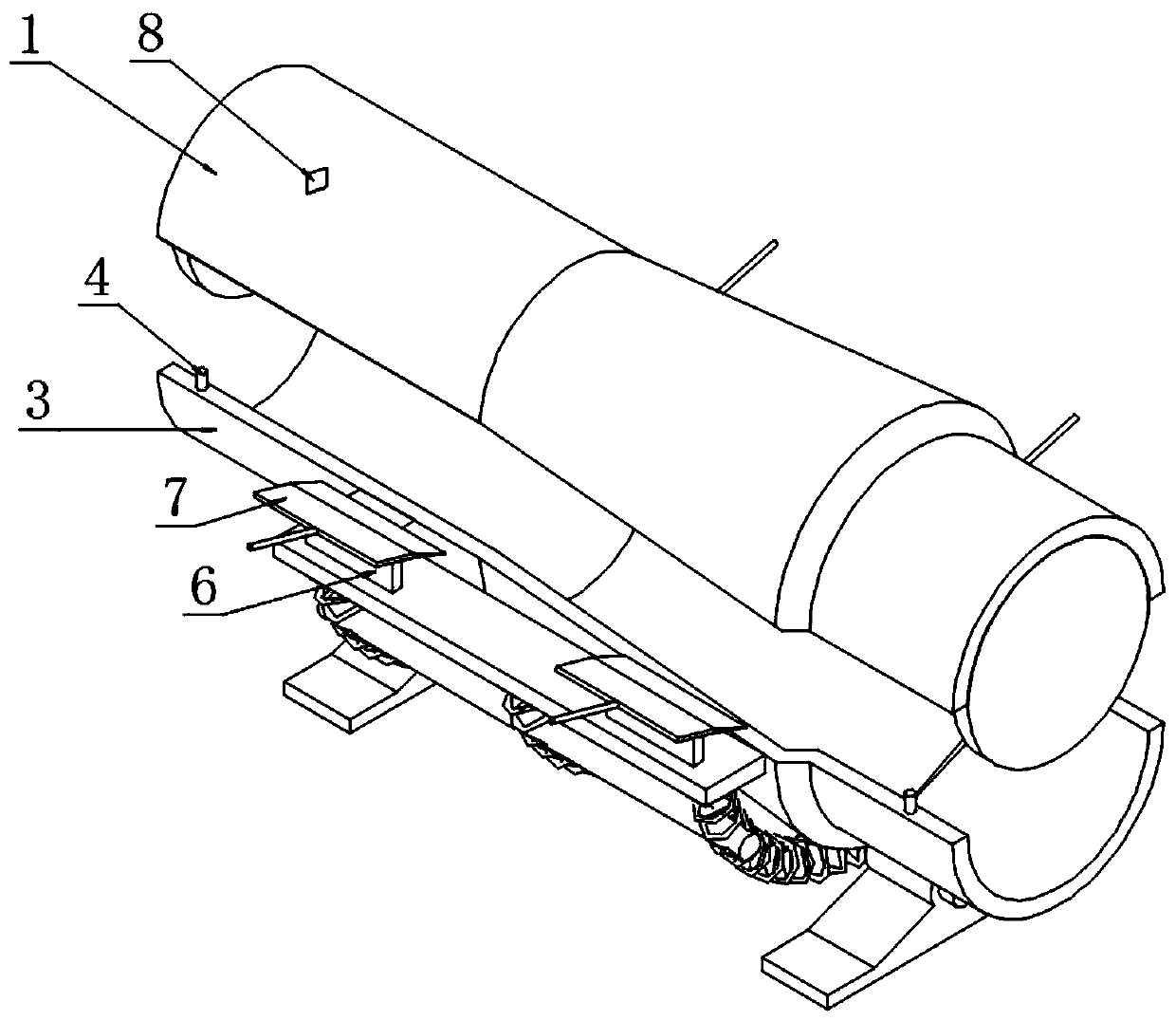
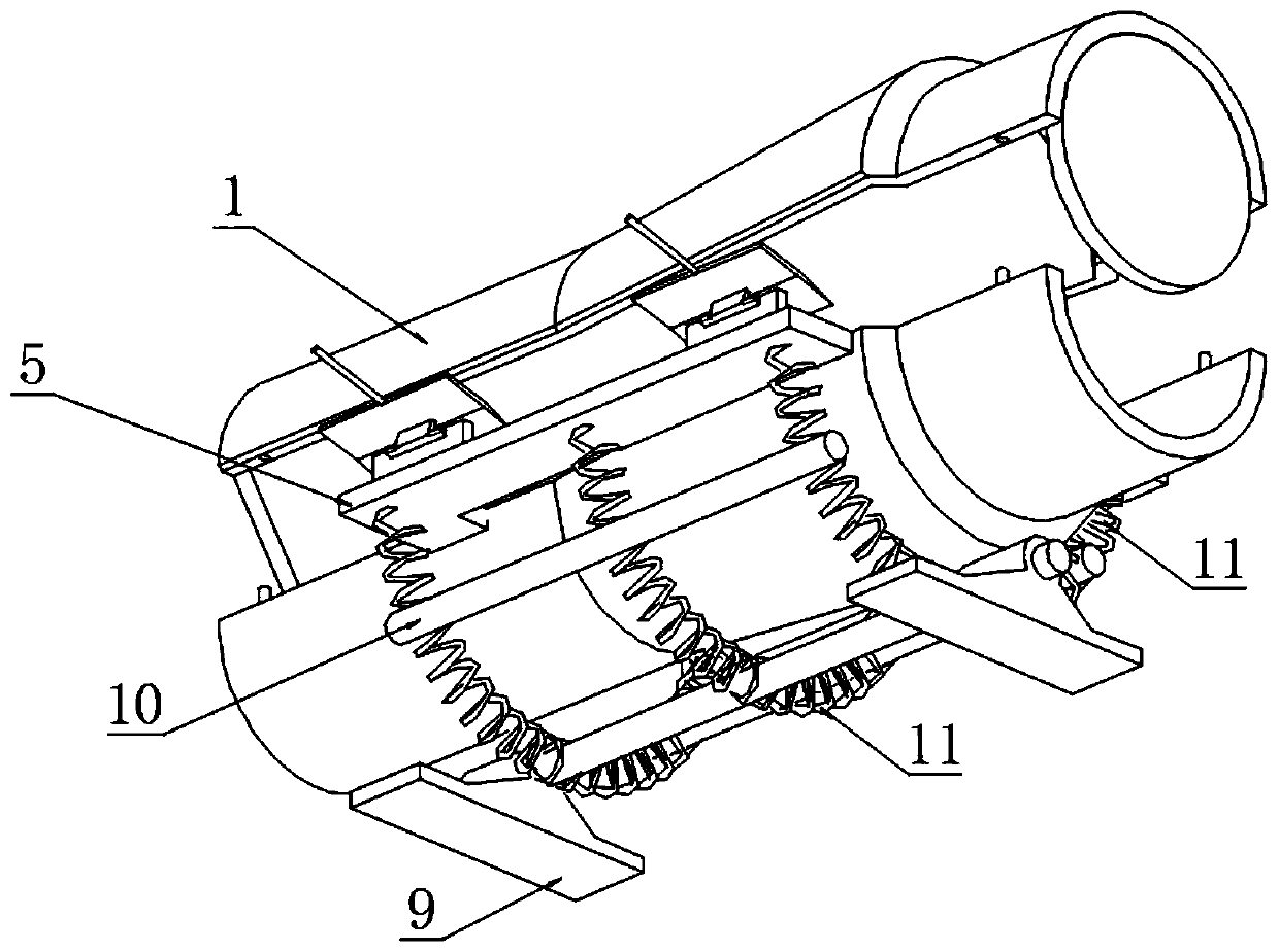
[0026] see Figure 1 to Figure 8 , an embodiment provided by the present invention: a split and foldable mandrel structure applied to injection molds, including a top cover 1; the top cover 1 is a stepped semicircular cavity structure, and its left and right ends are still A side plate 2 is welded, and a chamfered drop edge 16 is provided on both sides of the bottom surface of the top cover 1; two sockets 12 are provided on the bottom surface of the drop edge 16, and the top cover 1 is inserted through The holes 12 and the four sockets 4 welded on the top surface of the lower cover 3 matched with the structure of the bottom shell form a buckle butt joint, forming a c...


PUM


Abstract

The invention discloses a split conveniently-folded core rod structure applied to an injection mold, relates to the technical field of core rod structures for plastic molds, solves the problem that material shortage or sand holes occur on shaft shoulder parts of product parts in a stepped shaft mode due to uneven distribution of solution materials, and simultaneously improves the functional structure. The split conveniently-folded core rod structure applied to the injection mold comprises a top cover; the top cover is of a stepped semicircular cavity structure, and a side plate is welded at each of the left end and the right end of the top cover to form a complete stepped cavity structure; the situation that a shaft shoulder part of a stepped shaft part finally formed in the inner part isprone to having material shortage and sand hole conditions is reduced, a triangular warping groove is formed in the lower edge surface of the top cover, four warping plates are installed at the top ofa bottom cover in a mode of corresponding to the warping groove in a hinged mode, and after material liquid injected into a core rod cavity is formed into a product, if the top cover is not easy to move out, the top cover can be lifted up in a manner that the warping groove at the bottom of the top cover is pulled by the four warping plates, and the functional structure is improved.

Description

technical field [0001] The invention relates to the technical field of mandrel structures for plastic molds, in particular to a split and foldable mandrel structure applied to injection molds. Background technique [0002] Mandrel refers to: the part of the mold used to form the profile surface in the compact or sintered body in the pressing direction, and some mandrels are also directly used as mold cavities for injecting plastic solutions, such as our common plastic or rubber stepped shafts etc., is obtained by this process. [0003] Chinese patent application number CN201910418286.8 relates to a mandrel body electric heating injection blowing mandrel, which is composed of mandrel body, mandrel head, mandrel ejector rod, mandrel compression spring, star nut and cover nut. There is an air passage through the front and back inside the body. The two ends of the air passage are the air inlet and the air outlet. The rear end of the head is connected, the star nut and the cove...

Claims


Application Information

Patent Timeline
Patent Type & Authority Applications(China)
IPC IPC(8): B29C45/33B29C33/76
CPCB29C33/76B29C45/33
Inventor 杨玉成
Owner XIAMEN HUAYE PRECISE MOLD CO LTD
Learn More