Solid-liquid separation device for upper suspension type centrifugal machine

A solid-liquid separation and centrifuge technology, which is applied in the direction of filtration separation, separation method, mobile filter element filter, etc., can solve the problems of low recycling rate of water resources, low efficiency of solid-liquid separation, poor solid-liquid separation effect, etc. Achieve the effect of saving resources and cost, improving effect and improving separation efficiency

Pending Publication Date: 2020-02-18
JIANGSU PEONY CENTRIFUGE MFG
View PDF0 Cites 0 Cited by
  • Summary
  • Abstract
  • Description
  • Claims
  • Application Information

AI Technical Summary

Problems solved by technology

[0003] In order to overcome the deficiencies of the prior art, the object of the present invention is to provide a solid-liquid separation device for a top-hung centrifuge, which has the advantages of convenient operation, good vibration effect, good solid-liquid separation effect and high solid-liquid separation efficiency, The high recycling rate of water resources and the advantages of easy cleaning of the filter screen solve the problem that most of the traditional solid-liquid separation devices used in top-hung centrifuges are inconvenient to operate, the design structure is slightly simple, lack of vibration mechanism, and the solid-liquid separation effect is poor Moreover, the efficiency of solid-liquid separation is low, the recycling rate of water resources is low and the filter screen is difficult to clean.

Method used


Image

  • Solid-liquid separation device for upper suspension type centrifugal machine
  • Solid-liquid separation device for upper suspension type centrifugal machine
  • Solid-liquid separation device for upper suspension type centrifugal machine

Examples


Embodiment Construction

[0021] The technical solutions of the invention will be clearly and completely described below in conjunction with the accompanying drawings. Apparently, the described embodiments are part of the embodiments of the invention, not all of them. Based on the embodiments of the invention, all other embodiments obtained by persons of ordinary skill in the art without making creative efforts belong to the protection scope of the invention.

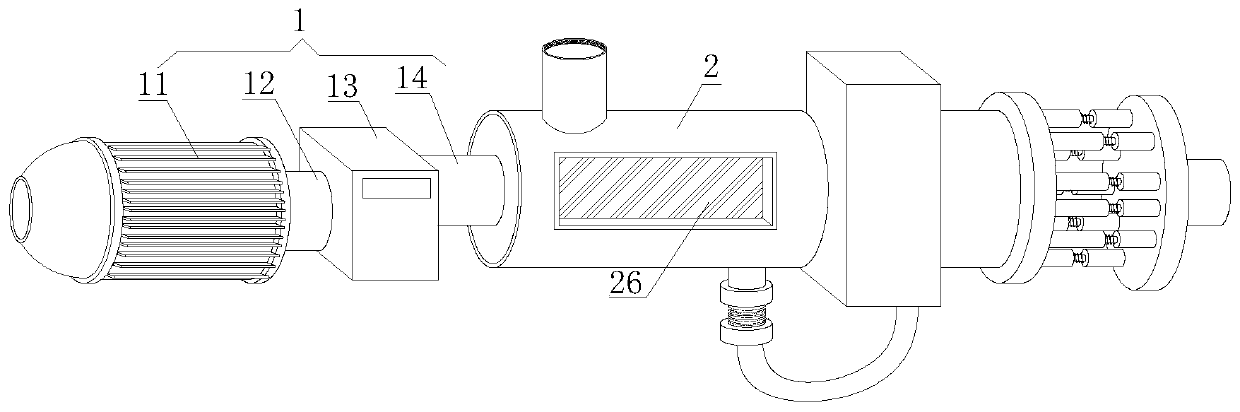
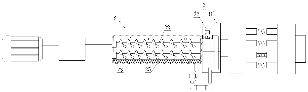
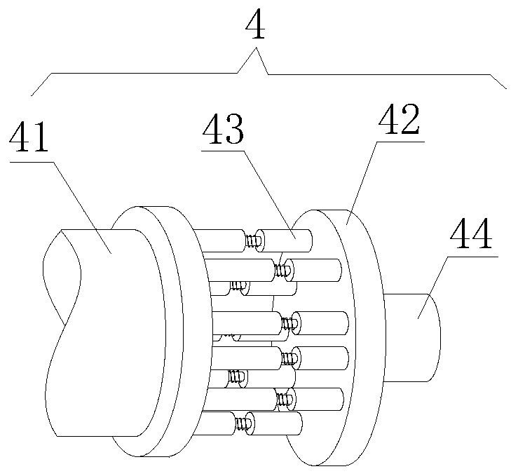
[0022] Such as figure 1 , figure 2 and Figure 5 As shown, a solid-liquid separation device for an overhead centrifuge includes a drive mechanism 1, a separation cylinder 2, a circulation mechanism 3, and a vibration mechanism 4. The drive mechanism 1 is installed on the left end of the separation cylinder 2, and the separation cylinder 2 The right end is connected with a circulation mechanism 3, and the right end of the circulation mechanism 3 is provided with a vibrating mechanism 4. The drive mechanism 1 includes a geared motor 11, a drive...


PUM


Abstract

The invention discloses a solid-liquid separation device for an upper suspension type centrifugal machine. The solid-liquid separation device comprises a driving mechanism, a separating cylinder, a circulating mechanism and a vibrating mechanism; the driving mechanism is mounted at the left end of the separation cylinder, the right end of the separation cylinder is connected with the circulating mechanism, and the vibrating mechanism is arranged at the right end of the circulating mechanism, so that the device has a certain vibrating effect while separating, some impurities on the filter screen can also be removed, and the solid-liquid separation effect is improved. According to the device, the circulating mechanism is connected to the right end of the separation cylinder, and the circulating mechanism comprises a circulating water tank and a cleaning device, so water separated by the device can be conveyed into the circulating water tank through the water conveying pipe, the water issprayed into an inner cavity of the separation cylinder by the cleaning device, the purpose of cleaning the device is achieved, resources and cost are saved, the practicability of the device is improved, and compared with similar products, the device is more unique in competition.

Description

technical field [0001] The invention belongs to the technical field of solid-liquid separation devices, and in particular relates to a solid-liquid separation device for an overhead centrifuge. Background technique [0002] The top suspension centrifuge is an advanced intermittent gravity, mechanical or manual unloading centrifuge. This series of centrifuges is advanced in design, reasonable in structure, stable in operation, easy to operate, high in production efficiency, large in processing capacity, and extremely maintenance-intensive. The disadvantage is that the whole machine is tall and needs a higher installation height. The main job of the top suspension centrifuge is solid-liquid separation. How can we achieve better solid-liquid separation effect? Most of the existing solid-liquid separation devices for top-hung centrifuges are not easy to operate, the design structure is slightly simple, lack of vibration mechanism, the solid-liquid separation effect is poor and ...

Claims


Application Information

Patent Timeline
Patent Type & Authority Applications(China)
IPC IPC(8): B01D33/03B01D33/48B01D33/68
CPCB01D33/0369B01D33/48B01D33/68
Inventor 顾坤一张威
Owner JIANGSU PEONY CENTRIFUGE MFG
Why Eureka
Try Eureka