
Cable traction winding device for ocean engineering

A cable traction and marine engineering technology, applied in cleaning methods and tools, cleaning methods using tools, chemical instruments and methods, etc., can solve the problem of motor loss, high energy consumption, and the inability to ensure close proximity of traction conduits, etc. problem, to achieve the effect of protecting the device, reducing friction and reducing resistance

Inactive Publication Date: 2020-03-17
QIANSHUI QINGYUAN HUBEI TECH CO LTD
View PDF0 Cites 3 Cited by
  • Summary
  • Abstract
  • Description
  • Claims
  • Application Information

AI Technical Summary

Problems solved by technology

[0003] When designing a marine cable traction and winding device, the traditional cable traction and winding device is driven by a motor to realize winding. When used on the ocean, because the length of the marine cable is too long, the motor needs to work for a long time. It not only loses the motor, but also requires a lot of energy consumption. At the same time, when the traditional cable traction and winding device is winding layer by layer, it cannot ensure that the traction conduit is close to the winding shaft and at the same time ensure that the traction conduit is winding Smooth movement on the spool

Method used

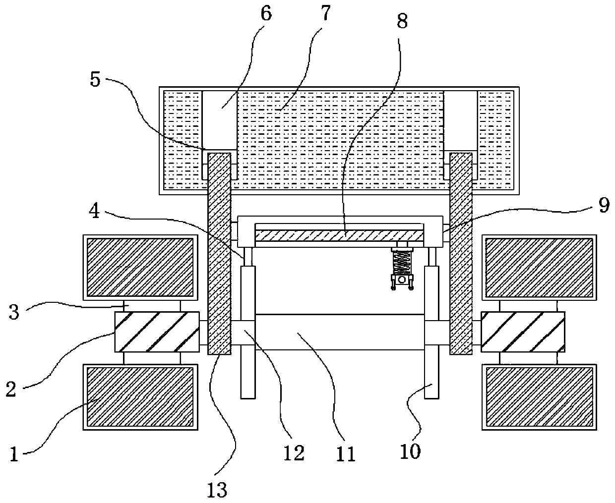

Image

  • Cable traction winding device for ocean engineering
  • Cable traction winding device for ocean engineering
  • Cable traction winding device for ocean engineering

Examples


Embodiment Construction

[0025] The following will clearly and completely describe the technical solutions in the embodiments of the present invention with reference to the accompanying drawings in the embodiments of the present invention. Obviously, the described embodiments are only some, not all, embodiments of the present invention.

[0026] In describing the present invention, it should be understood that the terms "upper", "lower", "front", "rear", "left", "right", "top", "bottom", "inner", " The orientation or positional relationship indicated by "outside", etc. is based on the orientation or positional relationship shown in the drawings, and is only for the convenience of describing the present invention and simplifying the description, rather than indicating or implying that the referred device or element must have a specific orientation, so as to Specific orientation configurations and operations, therefore, are not to be construed as limitations on the invention.

[0027] refer to Figure ...


PUM


Abstract

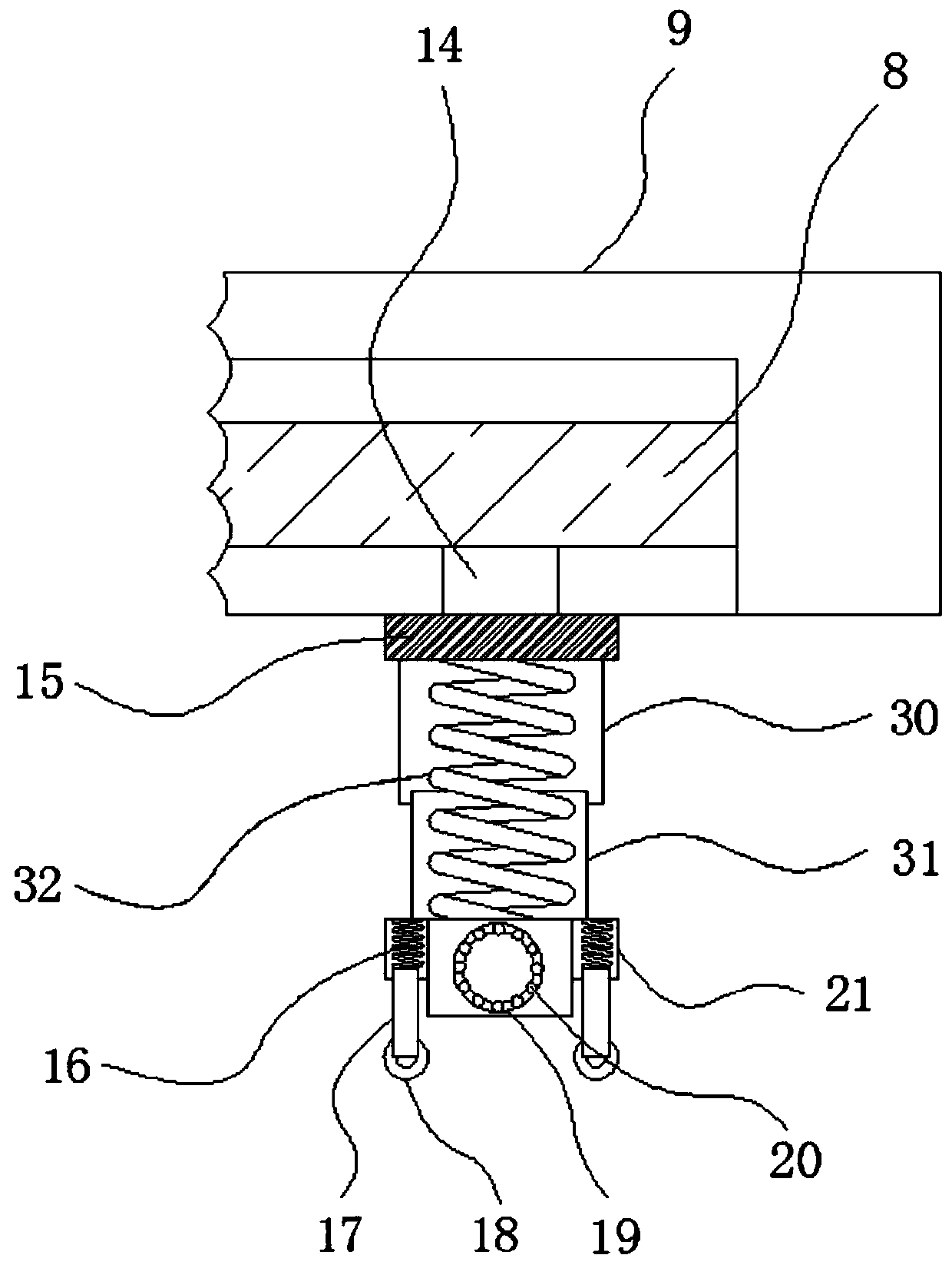
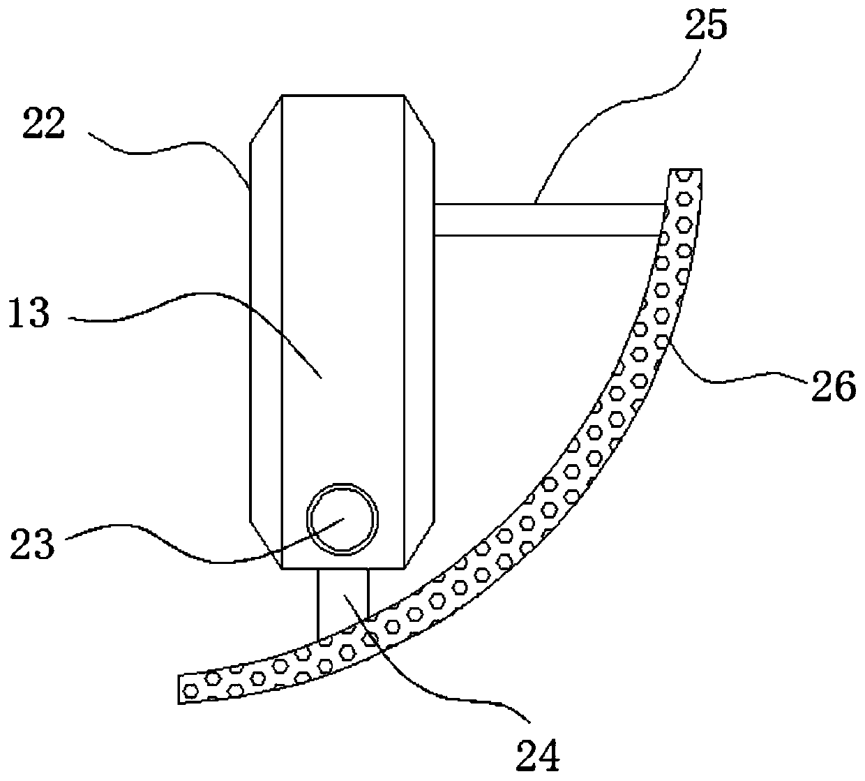
The invention belongs to the technical field of ocean engineering, and particularly relates to a cable traction winding device for ocean engineering. The cable traction winding device aims at solvingthe problems that a cable traction winding device in the prior art is driven by a motor to wind cables, and energy consumption is large. According to the scheme, the cable traction winding device comprises a supporting base, first grooves are formed in the outer walls of the two sides of one end of the supporting base, the inner walls of the two first grooves are connected with first electric guide rails through bolts, the outer wall of one end of each of the two first electric guide rails is in sliding connection with a first electric sliding block, and the outer walls of the other ends of the two first electric sliding blocks are connected with third supporting columns through bolts. According to the cable traction winding device for ocean engineering, a water baffle and a winding shaftare arranged, the supporting base is fixed to a stern, and in the ship moving process, water flow drives the water baffle to rotate, then the winding shaft is driven to rotate, the winding effect is achieved, and compared with traditional winding conducted through motor rotation, the energy is greatly saved.

Description

technical field [0001] The invention relates to the technical field of marine engineering, in particular to a cable traction and winding device for marine engineering. Background technique [0002] In the process of development, utilization and protection of the ocean, many new buildings and devices need to be built on the ocean. When supplying power to these buildings and devices, it is often necessary to conduct electricity through cables. However, the lines in the ocean The cable needs to be repaired and replaced after long-term use. In addition, after the development and research in some sea areas are completed, the sea area needs to be replaced, and then the cable needs to be put away. The above operations require pulling and winding the cable, so it is necessary to use To a cable pulling and winding device. [0003] When designing a marine cable traction and winding device, the traditional cable traction and winding device is driven by a motor to realize winding. When...

Claims


Application Information

Patent Timeline
Patent Type & Authority Applications(China)
IPC IPC(8): B65H75/44B65H75/42B08B1/02B08B1/20
CPCB65H75/4486B65H75/425B65H75/44B65H75/4405B65H2701/34B08B1/12B08B1/20
Inventor 陆朝阳
Owner QIANSHUI QINGYUAN HUBEI TECH CO LTD
Learn More