Printing paper winding device
A technology of winding device and printing paper, which is applied in the direction of winding strips, transportation and packaging, and thin material processing, etc., to achieve the effect of improving the clamping effect, stabilizing the position, and improving the applicable effect
Pending Publication Date: 2022-06-10
张圣南
View PDF0 Cites 0 Cited by
- Summary
- Abstract
- Description
- Claims
- Application Information
AI Technical Summary
Problems solved by technology
[0004]The purpose of the present invention is to solve the problem of poor applicability of existing smoothing rollers, and propose a printing paper winding device
Method used
View moreImage
Smart ImageViewing Examples
Examples
Embodiment 1
Embodiment 2
Login to View More PUM
 Abstract
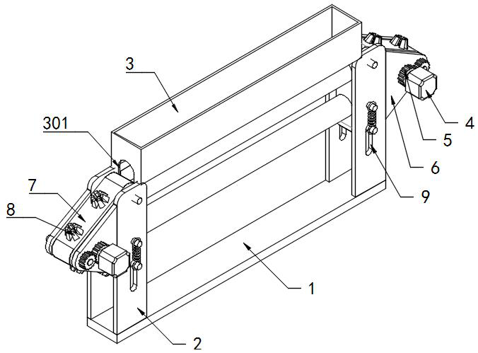
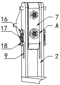
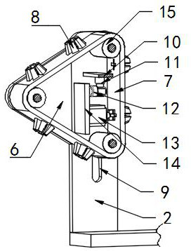
The printing paper winding device comprises a bottom plate, a stand column and a conveying belt mechanism, the conveying belt mechanism comprises a plurality of connecting plates, two connecting rods are fixedly connected to one ends of the connecting plates, two connecting grooves are formed in the other ends of the connecting plates, the connecting rods are inserted into the connecting grooves, and movable grooves are formed in the sides, close to the connecting grooves, of the connecting plates; the movable groove is in sliding connection with the plug pin of the next connecting plate, and the plug pin is elastically connected with the connecting plate through a first extension spring. According to the printing device, as the diameter of the printing paper roller is increased, the distance between the connecting plates forming the conveying belt mechanism is increased, a plug pin on a connecting rod of the next connecting plate slides in a movable groove, and therefore the distance between the two connecting plates is increased to adapt to movement of a clamping mechanism; and the printing paper wound on the winding roller is attached to the previous winding roller all the time, so that the printing paper is smoothed through the previous winding roller, and the application effect of the device is improved.
Description
Technical field [0001] The invention involves the field of printing technology and especially involves a printing paper collection device. Background technique [0002] Printing paper: The collective name for paper used for various prints.For example, convex printing paper, glue printing paper, high -grade shiny card paper, news paper, writing paper, etc.Its characteristic is that the printing adaptability and high opaqueity; the collection part of the roll processing production line, the raw materials are collected into rolls through mechanical methods, and they are widely used in paper rolls, cloth rolls, plastic rolls, metal coil processingOn the production line, it is designed to be diversified according to the actual process requirements. Commonly includes simple rolling machines, hydraulic rolling machines, and rolling machines generally have inner diameter, roll diameter, roll material thickness, width, and strict requirements. [0003] After the production of printing pap...
Claims
Login to View More Application Information
Patent Timeline
 Patent Type & Authority Applications(China)
IPC IPC(8): B65H23/34B65H23/16B65H18/26B65H18/02B65H18/10
CPCB65H23/34B65H23/16B65H18/26B65H18/028B65H18/10
Inventor 张圣南
Owner 张圣南
Features
- R&D
- Intellectual Property
- Life Sciences
- Materials
- Tech Scout
- Unparalleled Data Quality
- Higher Quality Content
- 60% Fewer Hallucinations
Learn More Browse by: Latest US Patents, China's latest patents, Technical Efficacy Thesaurus, Application Domain, Technology Topic, Popular Technical Reports.
© 2025 PatSnap. All rights reserved.Legal|Privacy policy|Modern Slavery Act Transparency Statement|Sitemap|About US| Contact US: help@patsnap.com


