Laser based frequency standards and their applications

Inactive Publication Date: 2007-04-19
IMRA AMERICA
View PDF29 Cites 165 Cited by
  • Summary
  • Abstract
  • Description
  • Claims
  • Application Information

AI Technical Summary

Benefits of technology

[0016] Other applications of low phase noise, high PRF fiber systems comprise wave meters, optical clocks, and sources of pulse trains with absolute phase stability. Low phase noise, high PRF fiber systems can further be effectively applied for the comparison of frequency standards at differ

Problems solved by technology

In contrast, other prior art modelocked fiber lasers are either limited in repetition rate or achievable timing jitter.
The lack of any bandpass filters in these systems restricts the operation of such systems to parabolic fiber lasers

Method used


Image

  • Laser based frequency standards and their applications
  • Laser based frequency standards and their applications
  • Laser based frequency standards and their applications

Examples


Embodiment Construction

[0032] For most applications of frequency combs, low noise operation of frequency comb lasers is preferred. Low noise dispersion compensated frequency comb sources are described in Fermann et al. '302, which is herein incorporated by reference. Applications of frequency comb sources as described in Fermann '302 greatly benefit from the availability of frequency combs that actually span more than one octave in the optical frequency spectrum.

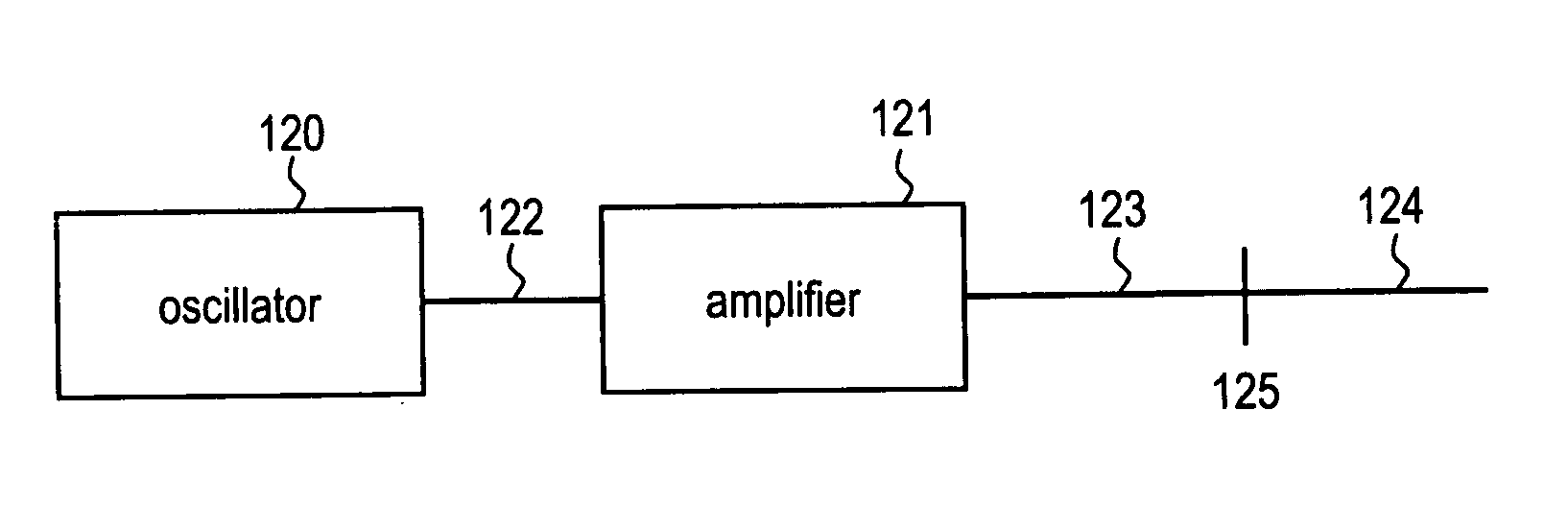
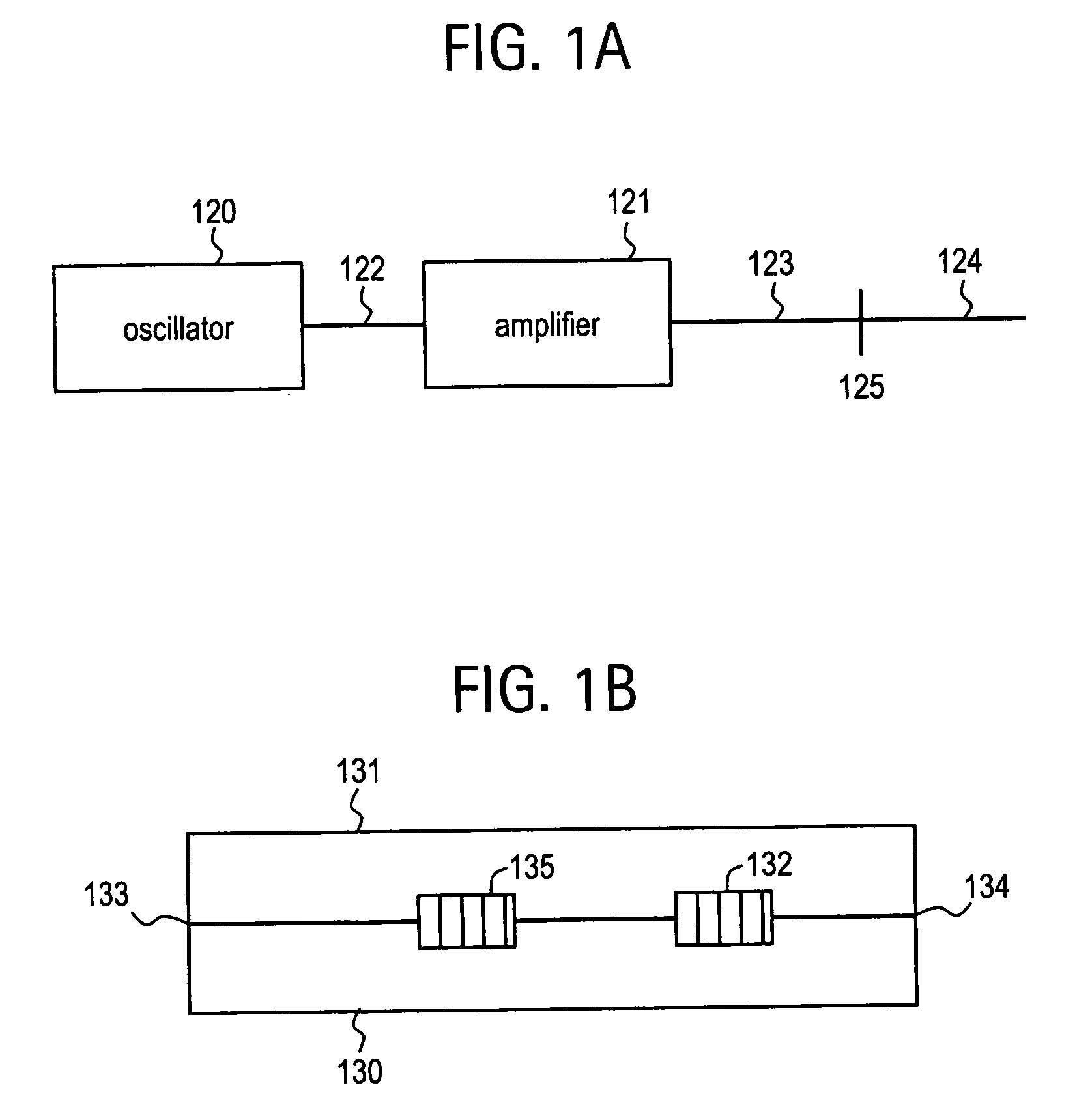
[0033] The generic design for an octave spanning comb source is shown in FIG. 1a. Such an octave spanning source typically comprises a modelocked fiber oscillator, whose output is further amplified in additional fiber amplifiers, where the amplified output is then injected into highly nonlinear fibers. An octave spanning spectrum typically is achieved once the output from the oscillator reaches the highly nonlinear fiber.

[0034] Here, oscillator 120 represents an oscillator design as previously described in the '302 publication. However, any othe...


PUM


Abstract

Frequency standards based on mode-locked fiber lasers, fiber amplifiers and fiber-based ultra-broad bandwidth light sources, and applications of the same.

Description

BACKGROUND OF THE INVENTION [0001] 1. Field of the Invention [0002] The invention relates to frequency standards based on mode-locked fiber lasers, fiber amplifiers and fiber-based ultra-broad bandwidth light sources, and applications of the same. [0003] 2. Description of the Prior Art [0004] Mode-locked fiber lasers have several advantages over both mode-locked bulk solid state lasers and mode-locked diode lasers. Mode-locked fiber lasers offer typically superior noise properties compared to mode-locked diode lasers and can be packaged in smaller spaces than mode-locked bulk solid state lasers. Mode-locked fiber lasers can be produced with excellent thermal and mechanical stability. Passively mode-locked fiber lasers in particular can be constructed with few and inexpensive optical components, suitable for mass production, as disclosed in patent publication US 2004 / 0213302 to Fermann et al. [0005] The dispersion compensated fiber lasers as disclosed by Fermann et al. allow the cons...

Claims


Application Information

Patent Timeline
IPC IPC(8): G02B6/00
CPCG02F1/3558H01S3/067H01S3/1112G02F1/365G02F2203/56G02F2001/3528G02F1/3528H01S3/06716H01S2301/02
Inventor INGMAR, HARTLFERMANN, MARTIN
Owner IMRA AMERICA
Why Eureka
Try Eureka