Method and apparatus for current measurement in an electrical network, in particular a multiphase electrical network

Active Publication Date: 2010-03-25
ROBERT BOSCH GMBH
View PDF16 Cites 13 Cited by
  • Summary
  • Abstract
  • Description
  • Claims
  • Application Information

AI Technical Summary

Benefits of technology

[0016]In particular, it is provided that the phase selection is effected such that a deviation generated by the current measurement from a predetermined set-point vector becomes zero or is kept as small as possible. As a result, losses can be minimized.
[0017]It is advantageous if a current measurement vector effected by the current measurement is selected in terms of its phase relationship for minimizing the deviation. Various possibilities are available with respect t

Problems solved by technology

The effort and expense for this multiphase measurement array is correspondingly great.
Because

Method used


Image

  • Method and apparatus for current measurement in an electrical network, in particular a multiphase electrical network
  • Method and apparatus for current measurement in an electrical network, in particular a multiphase electrical network
  • Method and apparatus for current measurement in an electrical network, in particular a multiphase electrical network

Examples


Example

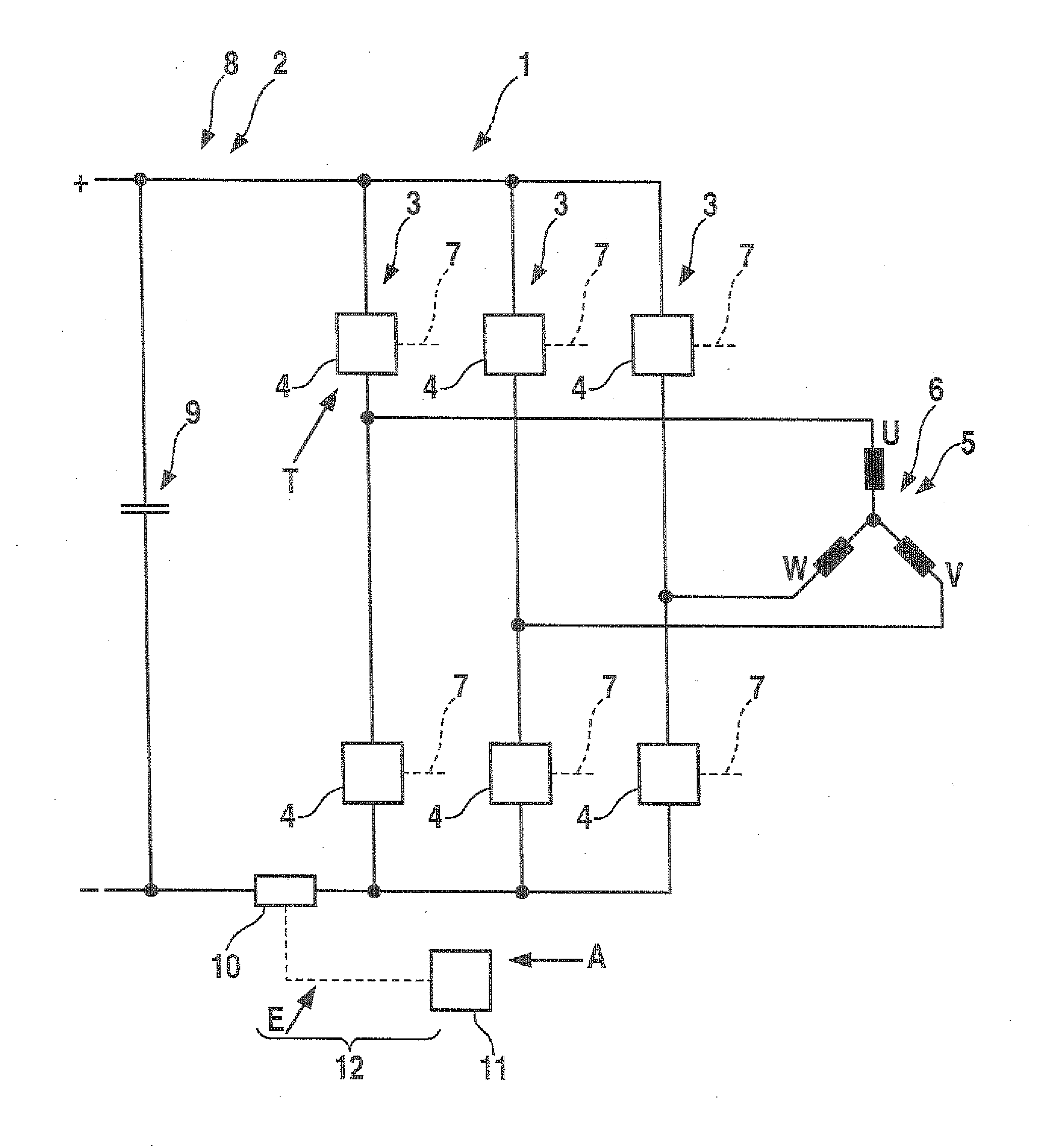
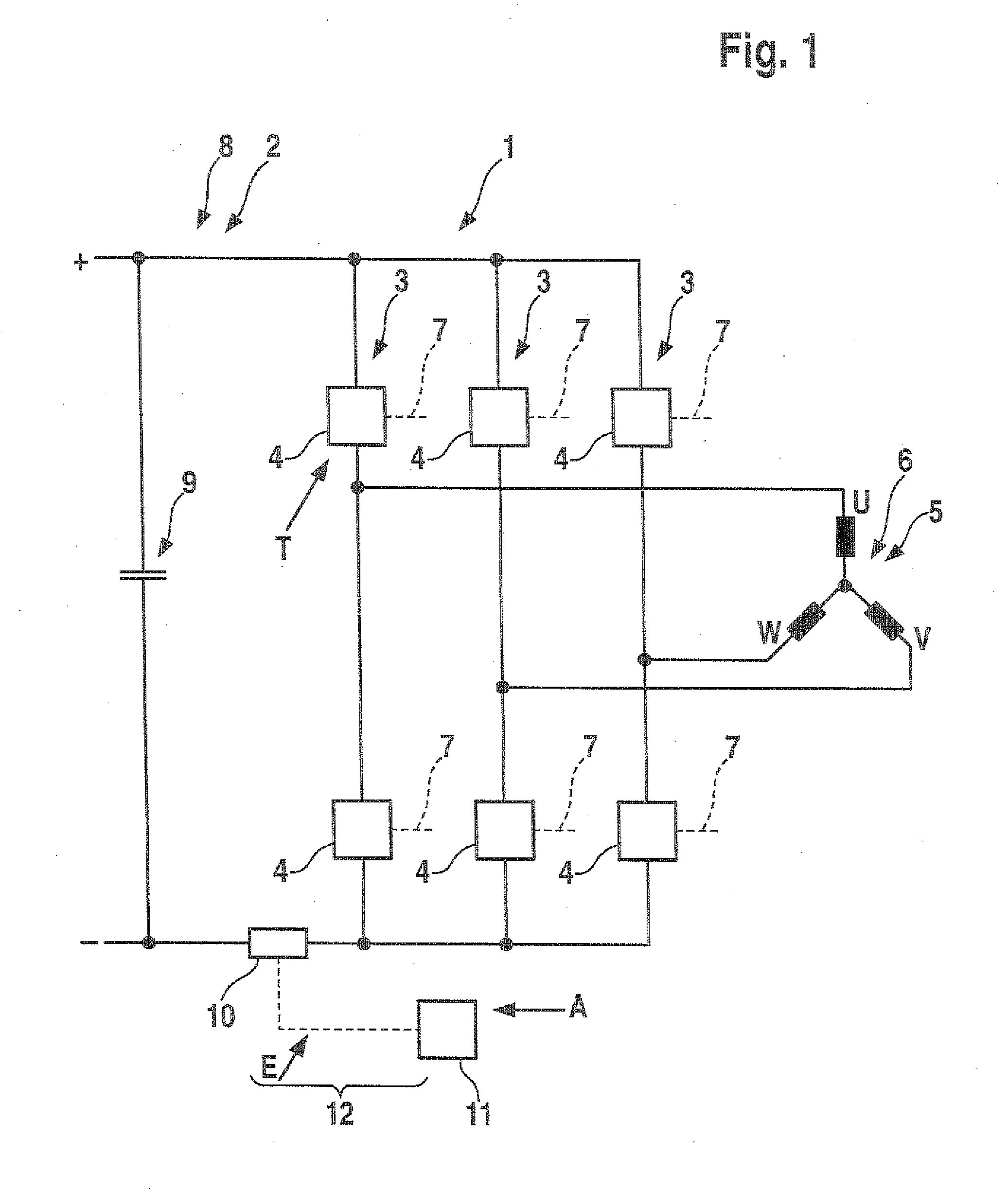
[0024]FIG. 1 shows a bridge circuit 1, which is connected to a DC circuit 2. The bridge circuit 1 is embodied as a B6 bridge, with three bridge branches 3. Each bridge branch 3 has two controllable circuit elements 4. A consumer 5, which is embodied as a three-phase asynchronous motor 6, is triggered by the bridge circuit 1. A control unit, not shown, generates trigger signals in accordance with certain timing patterns, and the trigger signals are delivered to control inputs 7 of the circuit elements 4, as a result of which the circuit elements can be switched into the conducting or the blocking state. In the DC circuit 2, which is embodied as a DC link circuit 8, there is a link circuit capacitor 9. The DC circuit 2 is connected to the bridge circuit 1 via a shunt 10.

[0025]In the procedure according to the invention, there is a single shunt 10, with which the phase currents of the asynchronous motor 6 can be ascertained in sequential order. Preferably, two phase currents of the tot...


PUM


Abstract

The invention relates to a method for current measurement in an in particular multiphase electrical system, in which an electrical load is energized as desired by at least one circuit element and a control unit produces drive signals which act on the at least one circuit element in order to achieve the desired energization of the load. The invention provides that clock patterns of the drive signals are associated with measurement windows for current measurement, in particular for measuring phase currents, and clock patterns are temporally offset in order to obtain measurement windows with a sufficient temporal length. A minimum temporal shift is the sum of a minimum dead time of the circuit element, a minimum settling time of the measuring amplifier circuit, and a minimum sampling time of the analogue-to-digital converter. The invention furthermore provides that the clock patterns are selected taking into consideration a phase selection for the current measurement. Provision may be made for the clock patterns to be selected taking into consideration the instantaneous rotary angle position of the phase vector. In addition, a corresponding apparatus is specified.

Description

[0001]The invention relates to a method for current measurement in a electrical network, in particular a multiphase electrical network.PRIOR ART[0002]In electric motors with multiphase triggering, there is often a demand for detecting the phase currents. If this involves energization of an electric motor by means of a controllable bridge that has controllable circuit elements in its individual bridge branches, then the electric motor can be energized in the desired way. To detect the phase currents, a low-impedance resistor (shunt) is disposed in each phase line. The effort and expense for this multiphase measurement array is correspondingly great.[0003]It is the object of the invention to make very simple, economical current measurement possible, and in particular little or no noise should occur from the measurement intervention and there should also be little or no torque waviness. Moreover, any components involved, such as link circuit capacitors, should be loaded only slightly.[...

Claims


Application Information

Patent Timeline
IPC IPC(8): G01R25/00G01R1/30
CPCH02M7/53875H02M7/5395H02M2001/0009H02M1/0009
Inventor SCHMITT, GILLESFINKE, SVENKURFISS, JOCHEN
Owner ROBERT BOSCH GMBH
Why Eureka
Try Eureka