Electrical Power Transmission Network

Active Publication Date: 2016-04-28
ROSENDAHL GLENN KENTON
View PDF8 Cites 12 Cited by
  • Summary
  • Abstract
  • Description
  • Claims
  • Application Information

AI Technical Summary

Benefits of technology

[0029]The arrangement as described herein therefore uses a bottom up approach to power system compensation and monitoring. Instead of one large installation, many thousands of small units are distributed across a system, ideally at individual power services or loads. Point of load compensation (PLC) is the optimal placement to minimize losses and maximize system stability. Several design factors contribute to dramatically reduce costs when compared with top down solutions.
[0030]Designing compensation equipment for the low voltage side reduces component costs, increases reliability and component availability. Installation costs are minimal using well established models from the telecommunications industry.
[0031]Typical distances from substation to load are many kilometers and the top down compensation has limited effect on these transmission lines. Installing compensation closer to loads and finer resolution of compensation reduce losses even further and increases system stability and flexibility.
[0032]Deployment of these devices at the point of load gives rise to a natural communication network, the power system voltages, currents, and phasors themselves. A global communication network is provided for overall system control and synchronization. But in the absence of global communication, individual units operate as a reflexive type of control, monitoring the power system's line values and reacting to changes with best operating practices. By providing a much faster response to disturbances than a traditional system, both system stability and availability is increased. This network of power monitors and compensators gives a unique insight into the workings of each installation. Using thi

Problems solved by technology

The most challenging problems power systems face today are; power factor control, transformer load imbalance, and nonlinear loads, adding to transformer imbalance and inject disruptive harmonic currents into the system.
All of these problems erode the efficiency and stability of the power system, in some cases over

Method used


Image

  • Electrical Power Transmission Network
  • Electrical Power Transmission Network
  • Electrical Power Transmission Network

Examples


Example

[0037]In the drawings like characters of reference indicate corresponding parts in the different figures.

DETAILED DESCRIPTION

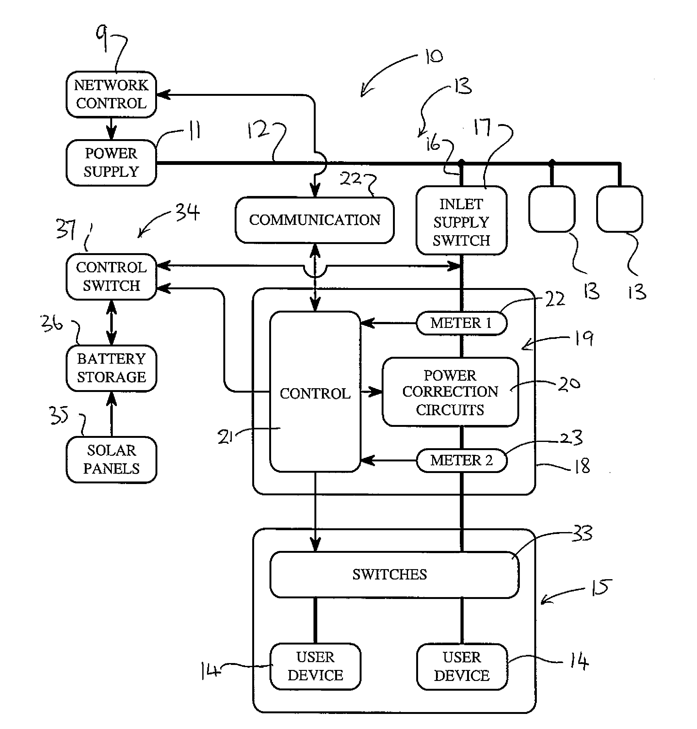
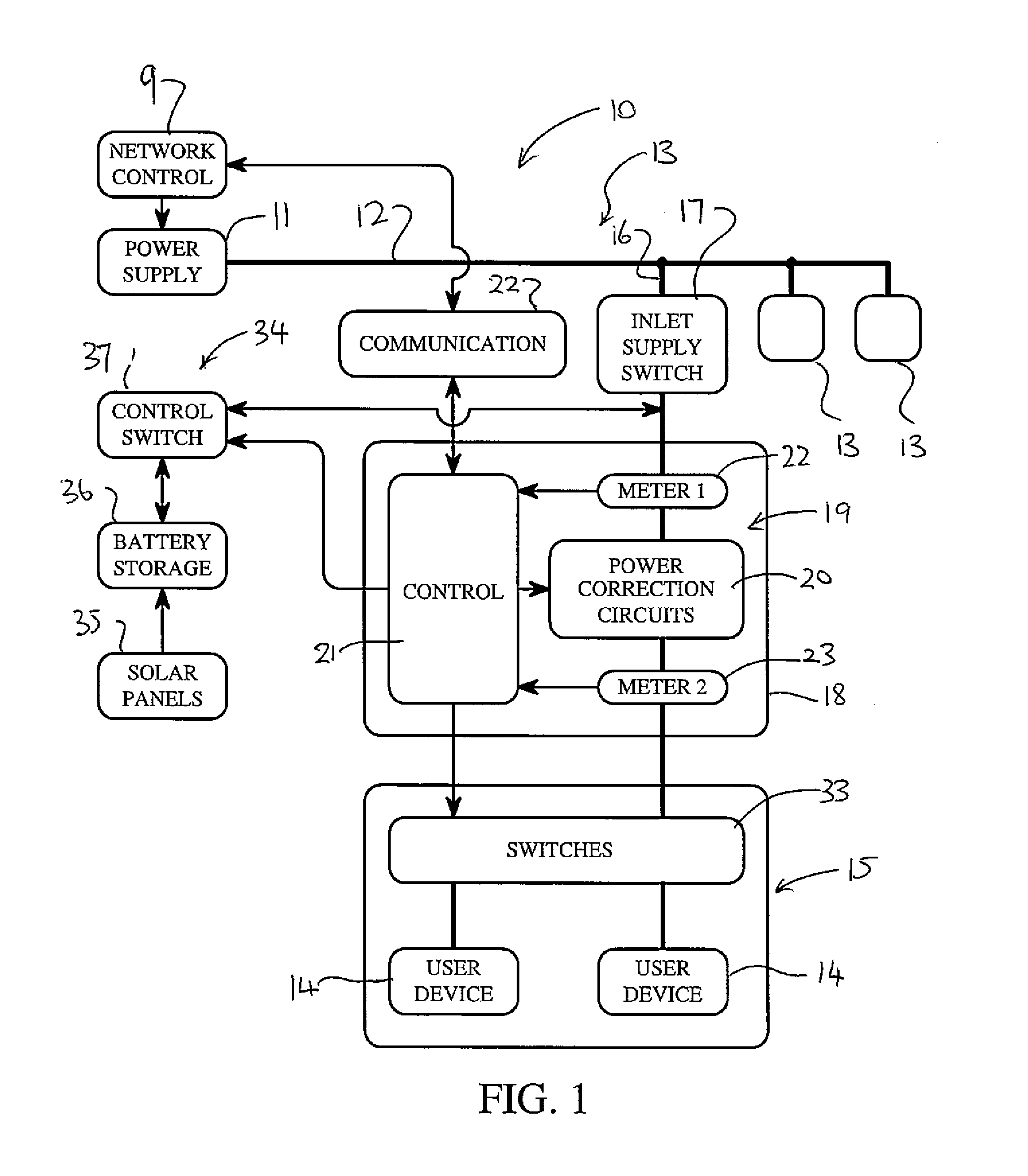
[0038]An electrical power transmission network 10 includes a power supply 11 generally at a transformer supplying one or more transmission lines 12 and managed by a network control system 9 using many systems for detecting parameters of the network and for controlling various components of the network to maintain voltage stability on the transmission lines.

[0039]On the transmission line is a plurality of subscriber premises 13 for receiving electrical power, each including a plurality of user devices 14 on a power supply circuit 15. Each of the subscriber premises 13 has a drop 16 from the transmission line to a power supply inlet board 17 typically including a main inlet control switch. Typically in the drop is provided a meter for measuring power usage. In the present invention the meter is replaced by an integral component defining a load control device 18 ...


PUM


Abstract

An improved management of an electrical power transmission network is obtained by providing at each of the subscriber premises a load control device which includes a power correction system for applying a capacitive load and/or a switched reactor for voltage correction across the input voltage and a sensing system defined by a pair of meters one at the supply and the second downstream of the voltage correction for detecting variations in power factor. A control system operates to control the power correction system in response to variations detected by the sensing system and to communicate between the load control device and the network control system so as to provide a bi-directional interactive system.

Description

[0001]This invention relates to an electrical power transmission network designed to compensate for the power factor which arises due to reactive loads on the network.BACKGROUND OF THE INVENTION[0002]The most challenging problems power systems face today are; power factor control, transformer load imbalance, and nonlinear loads, adding to transformer imbalance and inject disruptive harmonic currents into the system. All of these problems erode the efficiency and stability of the power system, in some cases over 40% of power is lost enroute to the customer.[0003]Power system compensation is presently done from the top down, high voltage and high power correction equipment is installed at distribution substations. This can include static or switched capacitor banks and / or switched reactors for power factor or voltage correction, universal power flow controllers to balance loads and control bus voltages. These devices can address some of the challenges but, the costs are significant an...

Claims


Application Information

Patent Timeline
IPC IPC(8): H02J3/14G05B15/02
CPCG05B15/02H02J3/14H02J3/16H02J3/18Y02E40/30Y04S20/222Y04S20/242Y02B70/30Y02B70/3225Y02E40/50
Inventor ROSENDAHL, GLENN KENTON
Owner ROSENDAHL GLENN KENTON
Why Eureka
Try Eureka