Charging system with a high temperature thermal energy exchange system and method for charging heat storage material of the high temperature thermal energy exchange system with thermal energy

Active Publication Date: 2017-09-14
SIEMENS GAMESA RENEWABLE ENERGY AS
View PDF0 Cites 15 Cited by
  • Summary
  • Abstract
  • Description
  • Claims
  • Application Information

AI Technical Summary

Benefits of technology

[0010]The charging unit is arranged such that an efficient heat transfer to the heat transfer fluid of the inflow is possible. In order to minimize loss of thermal energy, the charging unit is preferably arranged at the inlet opening (near by the inlet opening).
[0011]Preferably, the charging unit comprises at least one electrical heating device which is selected from the group consisting of resistance heater, inductive heater, emitter of electromagnetic radiation and heat pump. The electromagnetic radiation is preferably infrared radiation. With the aid of the resistance heater thermal energy is produced and transferred to the heat transfer fluid (via direct contact, convectio

Problems solved by technology

All other storage technologies are lacking capability to store electric energy at low cost, whereas pumped hydro storage is geographically limited to certain regions (sufficient geodetic heights).
The remaining heat is lost.
In contrast to that, natural convection leads to a non-uniform temperature front in a horizontal heat exchange chamber.
Weak grid nod

Method used


Image

  • Charging system with a high temperature thermal energy exchange system and method for charging heat storage material of the high temperature thermal energy exchange system with thermal energy
  • Charging system with a high temperature thermal energy exchange system and method for charging heat storage material of the high temperature thermal energy exchange system with thermal energy
  • Charging system with a high temperature thermal energy exchange system and method for charging heat storage material of the high temperature thermal energy exchange system with thermal energy

Examples


Embodiment Construction

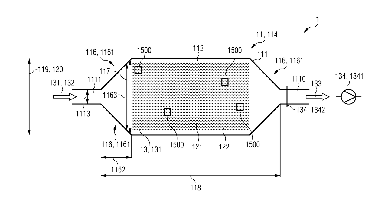
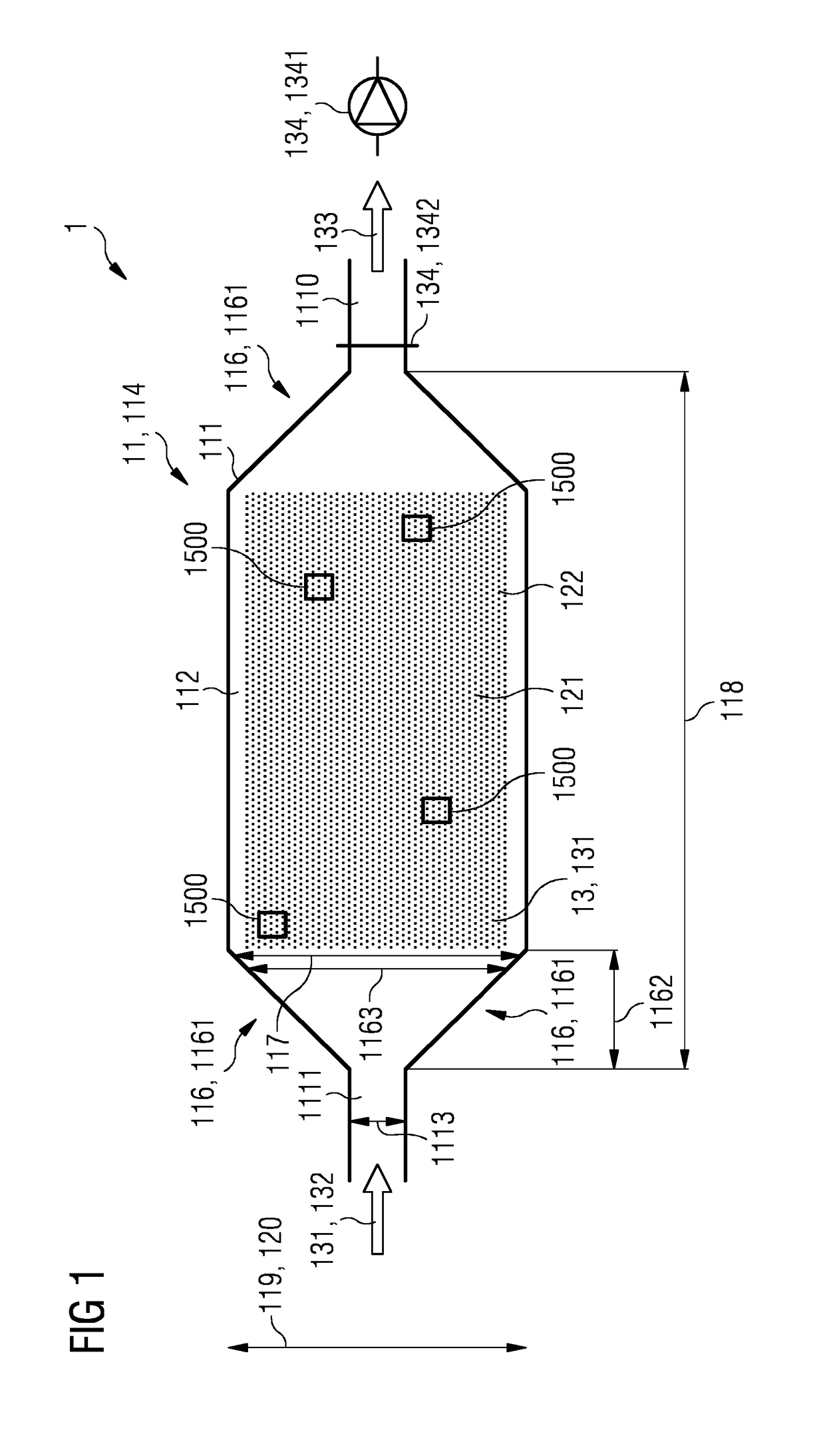
[0097]Given is a charging system 1000 with a least one high temperature thermal energy exchange system 1 with a heat exchange chamber 11 on a high temperature level, which will be charged and discharged with thermal energy via a heat transfer fluid 13 which is then stored in the heat storage material 121.

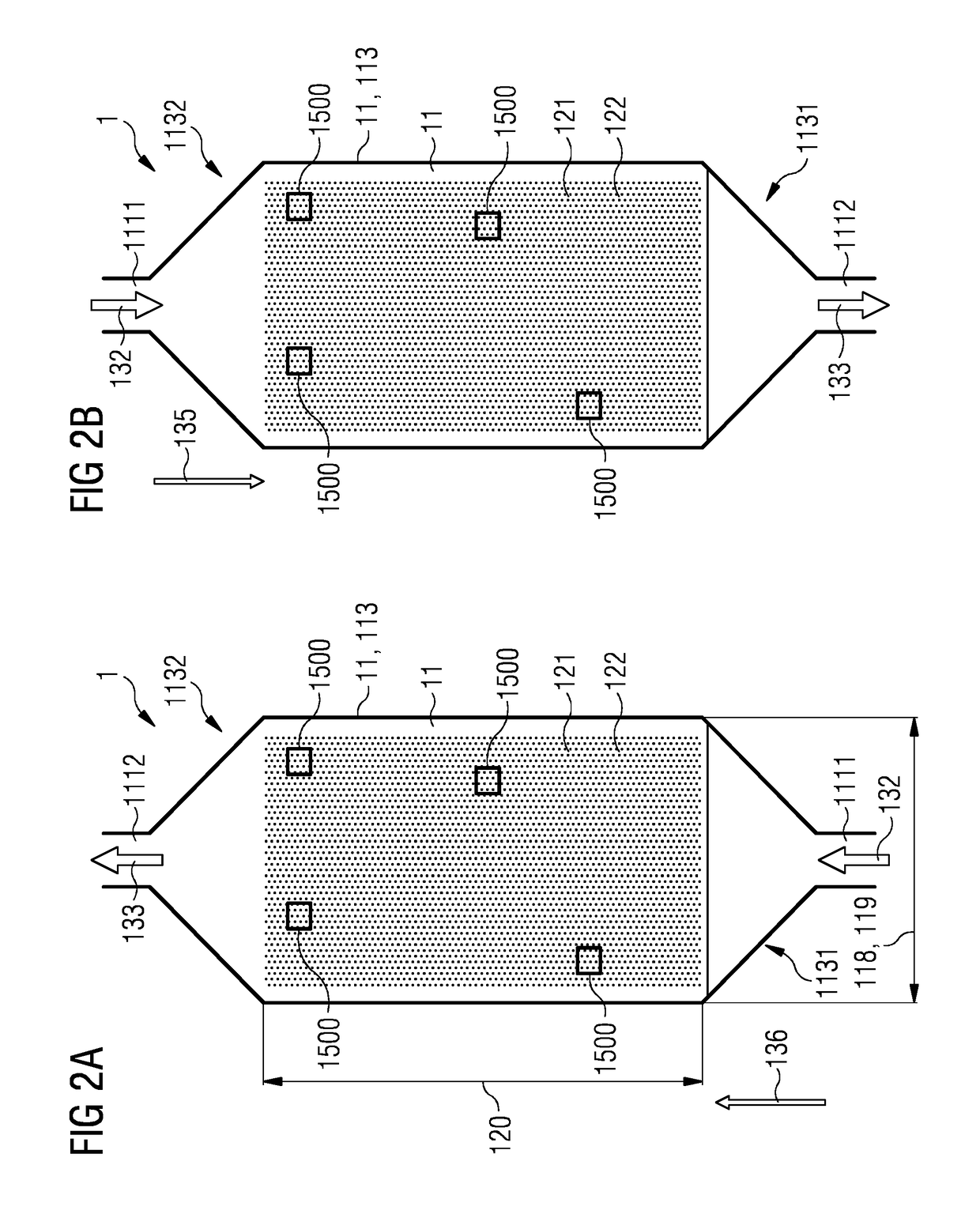
[0098]The high temperature thermal energy exchange system 1 comprises a heat exchange chamber 11 on a high temperature level, which will be charged and discharged with thermal energy via a heat transfer fluid 13 and stored in the heat storage material 121.

[0099]The temperature level of the stored heat is significantly higher compared to methods applied so far to increase the efficiency. The temperature level lies between 300° C. and 800° C., preferably between 550° C. and 650° C. The thermal capacity of the high temperature heat exchange system lies in the range between 0.3 GWh and 100 GWh, which causes a thermal power of 50 MW.

[0100]The high temperature thermal energy exchange syst...


PUM


Abstract

A charging system with a least one high temperature thermal energy exchange system is provided. The high temperature thermal energy exchange system includes at least one heat exchange chamber with chamber boundaries which surround at least one chamber interior of the heat exchange chamber, wherein the chamber boundaries include at least one inlet opening for guiding in an inflow of at least one heat transfer fluid into the chamber interior and at least one outlet opening for guiding out an outflow of the heat transfer fluid out of the chamber interior. At least one heat storage material is arranged in the heat exchange chamber interior such that a heat exchange flow of the heat transfer fluid through the heat exchange chamber interior causes a heat exchange between the heat storage material and the heat transfer fluid.

Description

CROSS-REFERENCE TO RELATED APPLICATIONS[0001]This application claims priority to PCT Application No. PCT / EP2015 / 055958, having a filing date of Mar. 20, 2015, based off of EP Application No. 14187085.7 having a filing date of Sep. 30, 2014, the entire contents of which are hereby incorporated by reference.FIELD OF TECHNOLOGY[0002]The following refers to a charging system with a high temperature thermal energy exchange system and a method for charging heat storage material of the high temperature thermal energy exchange system with thermal energy.BACKGROUND[0003]Despite the integration of renewable energy into the public electric energy system (power grid) a large share of electricity is nowadays still generated by fossil energy sources. But the global climate change requires the further development of renewable energies.[0004]The energy output of renewable energy sources like wind and solar is not constant throughout a day or throughout a year. Consequently, electricity which is gen...

Claims


Application Information

Patent Timeline
IPC IPC(8): F28D17/00F28D20/00
CPCF28D20/0056F28D17/005F01K3/00F28D20/02Y02E60/14
Inventor BARMEIER, TILL ANDREASSEIDEL, VOLKERSTIESDAL, HENRIK
Owner SIEMENS GAMESA RENEWABLE ENERGY AS
Why Eureka
Try Eureka