Bone treatment systems and methods for introducing an abrading structure to abrade bone

a bone and abraded technology, applied in the field of medical devices, can solve the problems of point loading, explosive expansion of the balloon, and easy cracking of the endplate, and achieve the effects of increasing the cross section of the path or space being created, and reducing the risk of fractur

Active Publication Date: 2010-03-23
DFINE INC
View PDF99 Cites 165 Cited by
  • Summary
  • Abstract
  • Description
  • Claims
  • Application Information

AI Technical Summary

Benefits of technology

[0021]In another embodiment of the invention, a probe system has a working end that comprises an expandable structure having an abrasive surface. In use, the expandable abrading surface is rotated at high speed to cut bone while being expanded to increase the cross section of the path or space being created. The use of the expandable cutter allows the treatment of bone with low pressures to create paths or spaces without explosive expansion forces known in prior art balloon procedures that are designed to crush and compact cancellous bone in a vertebra.
[0022]There is a general need to provide systems and methods for use in treatment of vertebral compression fractures that provide a greater degree of control over introduction of bone support material, and that provide better outcomes. The present invention meets this need and provides several other advantages in a novel and nonobvious manner.

Problems solved by technology

The explosive expansion of a kyphoplasty balloon can cause point loading where the balloon contacts the cortical endplates of the vertebra.
The explosive expansion of the balloon can easily crack an endplate if the expanded balloon wall is in close proximity to the endplate.

Method used


Image

  • Bone treatment systems and methods for introducing an abrading structure to abrade bone
  • Bone treatment systems and methods for introducing an abrading structure to abrade bone
  • Bone treatment systems and methods for introducing an abrading structure to abrade bone

Examples


Embodiment Construction

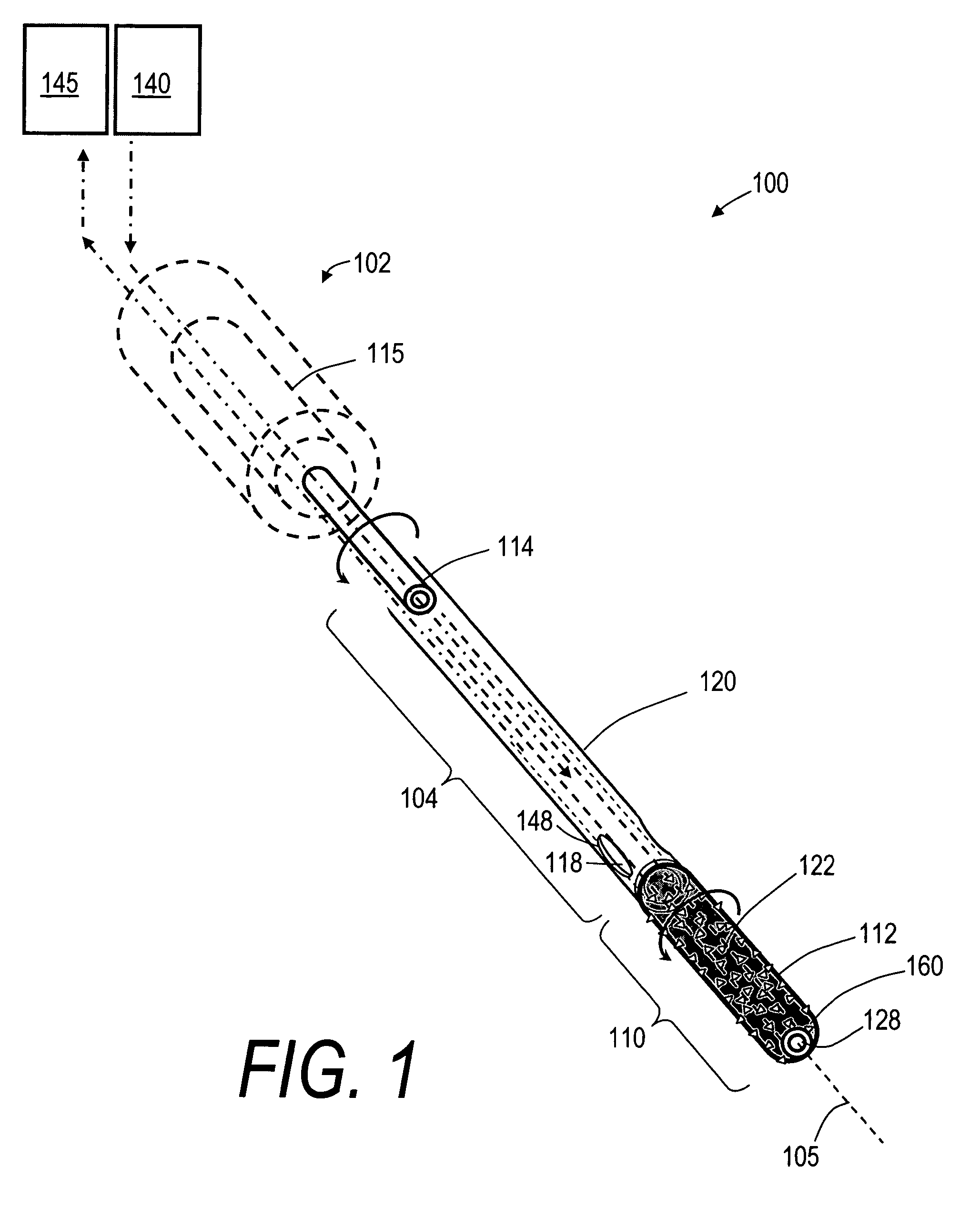
[0036]FIG. 1 is a schematic view of an exemplary bone cutting system or probe 100 that has handle portion 102 that transitions to elongated extension member 104 that extends along axis 105. The extension member 104 carries a distal working end 110 that comprises a high speed elastomeric, abrasive rotational-cutter indicated at 112. The handle portion 102 can be any suitable assembly for gripping with a human hand and can carry trigger and actuator mechanisms known in the art.

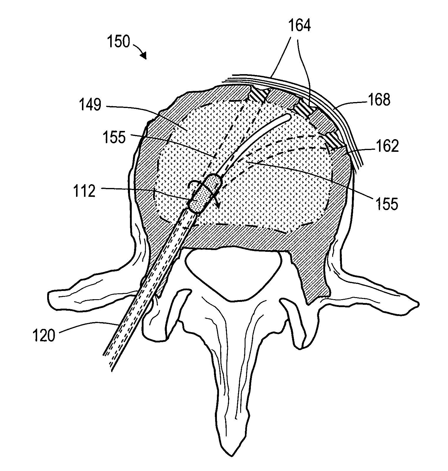
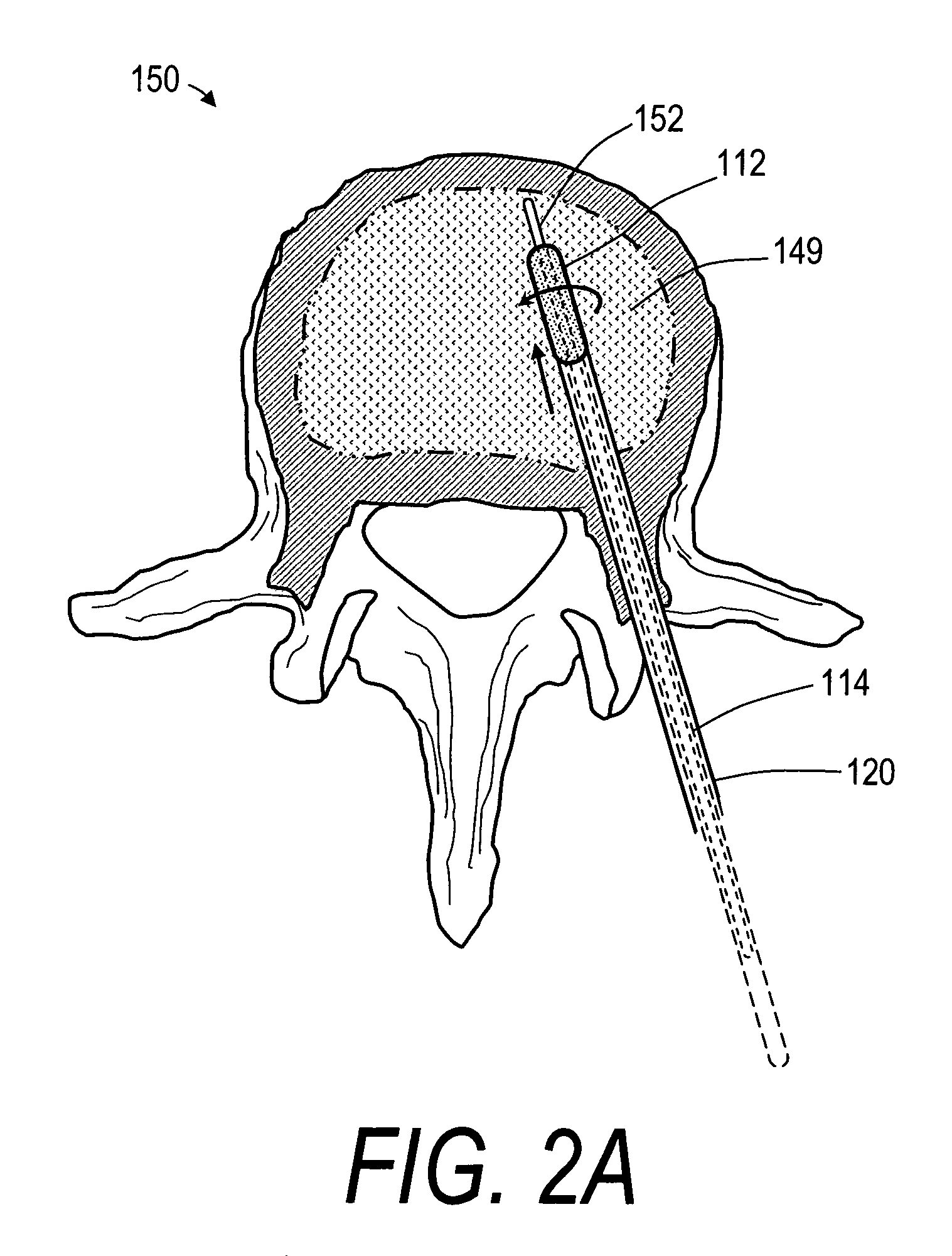
[0037]In the embodiment of FIG. 1, the elastomeric abrasive cutter 112 is fixedly coupled to the distal end of elongated drive member 114 that is rotated at a high speed by a rotation mechanism, such as an air motor or electric motor indicated at 115. The drive member 114 rotates in bore 118 in an elongated rigid sleeve 120 that is coupled to handle portion 102. The elongated sleeve 120 and elastomeric cutter 112 are configured with dimensions suited for insertion into a vertebra from a posterior transpedicular ...


PUM


Abstract

The invention provides instruments and methods for prophylactic treatment of an osteoporotic vertebral body or for treating a vertebral compression fracture (VCF). In one exemplary method, a probe system uses a high speed rotational elastomeric cutter having an optional expandable abrasive surface for abrading or cutting at least one path or region within vertebral cancellous bone. Irrigation and aspiration sources are included in the probe system for removing abraded bone debris. In one embodiment, the high speed rotational abrader uses a tissue-selective abrading surface that abrades or cuts bone but does not cut soft tissue. In another embodiment, an expandable abrading surface allows the treatment of bone with low pressures to create paths or spaces without explosive expansion forces known in prior art balloon procedures that are designed to crush and compact cancellous bone in a vertebra. After the creation of a path or space, an in-situ hardenable bone cement volume is introduced into each path or space to support the vertebra.

Description

CROSS-REFERENCE TO RELATED APPLICATIONS[0001]This application claims benefit of Provisional U.S. Patent Application Ser. No. 60 / 626,786 filed Nov. 10, 2004 titled Systems and Methods for Treating Vertebral Fractures. This application also is related to U.S. application Ser. No. 11 / 165,652 filed Jun. 24, 2005 titled Bone Treatment Systems and Methods; and U.S. patent application Ser. No. 11 / 165,651 filed Jun. 24, 2005, titled Bone Treatment Systems and Methods. The entire contents of all of the above cross-referenced applications are hereby incorporated by reference in their entirety and should be considered a part of this specification.BACKGROUND OF THE INVENTION[0002]1. Field of the Invention[0003]The present invention relates to medical devices, and more particularly to methods and apparatus for treating an abnormal vertebra. More particularly, an apparatus and method includes using a probe carrying a tissue-selective elastomeric rotational cutter having an abrasive surface for ab...

Claims


Application Information

Patent Timeline
Patent Type & Authority Patents(United States)
IPC IPC(8): A61B17/88
CPCA61B17/1615A61B17/1617A61B17/1631A61B17/1642A61B17/1671A61B17/32002A61M1/0082A61B17/1668A61B17/320725A61B2017/00261A61B2017/00557A61B2017/320004A61B2217/005A61B2217/007A61M1/842
Inventor TRUCKAI, CSABASHADDUCK, JOHN H.
Owner DFINE INC
Why Eureka
Try Eureka