Spinal stabilization systems and methods

a technology of spinal stabilization and spinal cord, applied in the field of spinal stabilization systems and methods, can solve the problems of increasing the incidence of spinal disorders, the costliest and most debilitating health problems, and the inability to stabilize the spinal cord, and achieve the effect of relieving the pressure of the dis

Inactive Publication Date: 2007-04-12
SPINAL KINETICS
View PDF58 Cites 160 Cited by
  • Summary
  • Abstract
  • Description
  • Claims
  • Application Information

AI Technical Summary

Benefits of technology

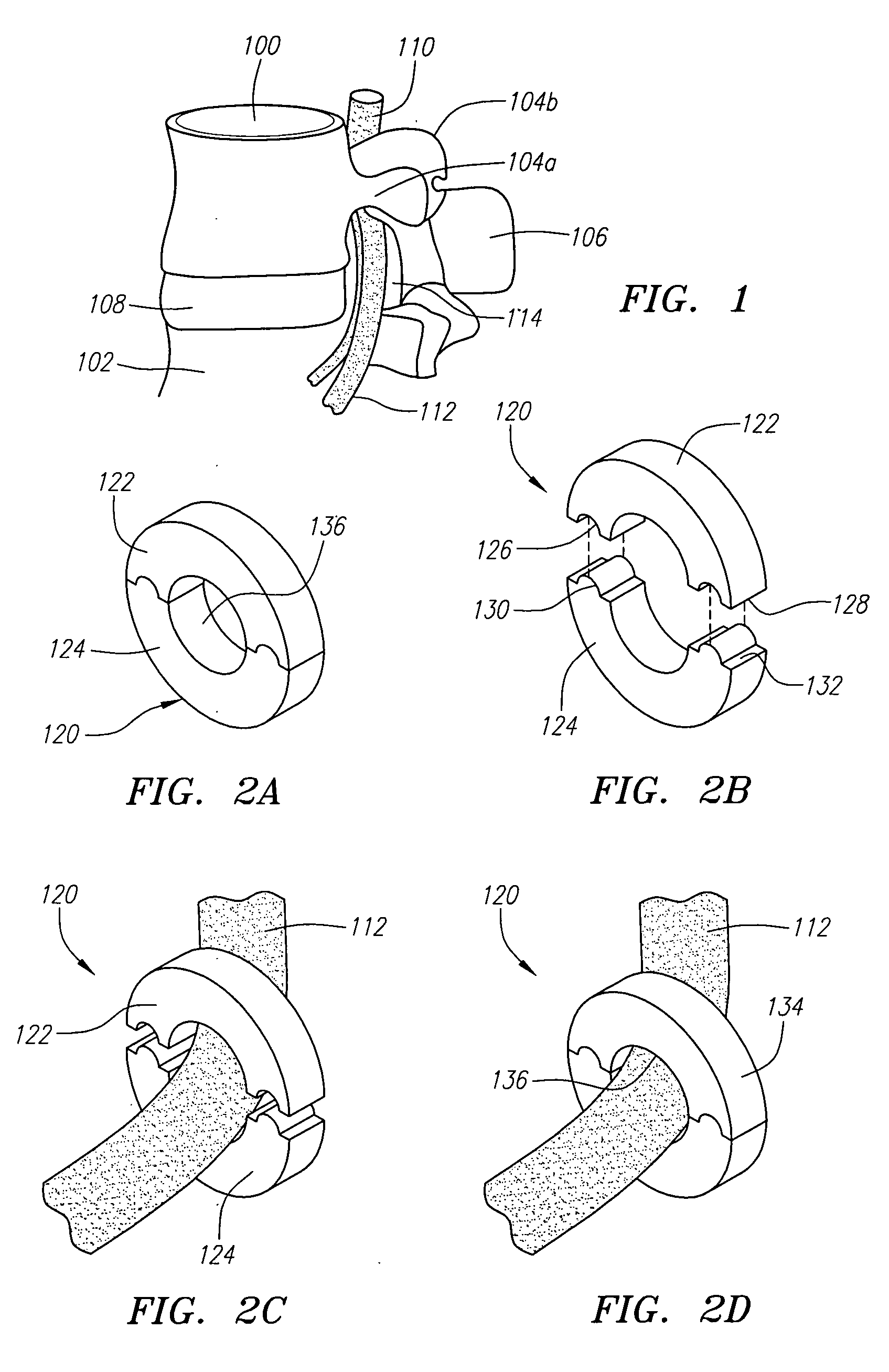
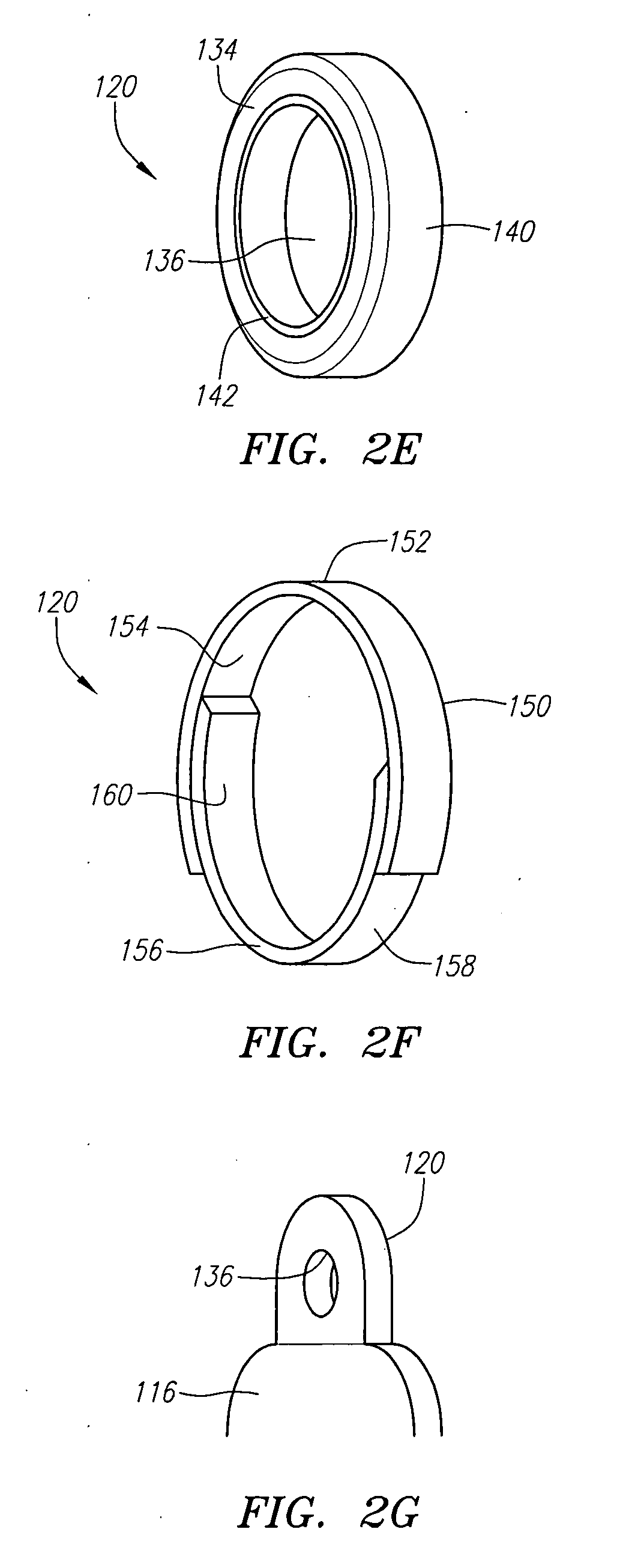
[0011] Preferably, the foramenal spacer is formed of a rigid biocompatible material, such as stainless steel, metal alloys, or other metallic materials, or a rigid polymeric material. In alternative embodiments, the foramenal spacer is provided with an outer layer formed of a soft, conformable material (e.g., an elastomeric polymer such as polyurethane) that provides conformability with the foramen geometry and allows flexion, extension and lateral bending of the spine. In still other embodiments, the foramenal spacer includes an inner liner formed of a soft and / or low-friction material to provide an atraumatic surface for passage of the nerve root.
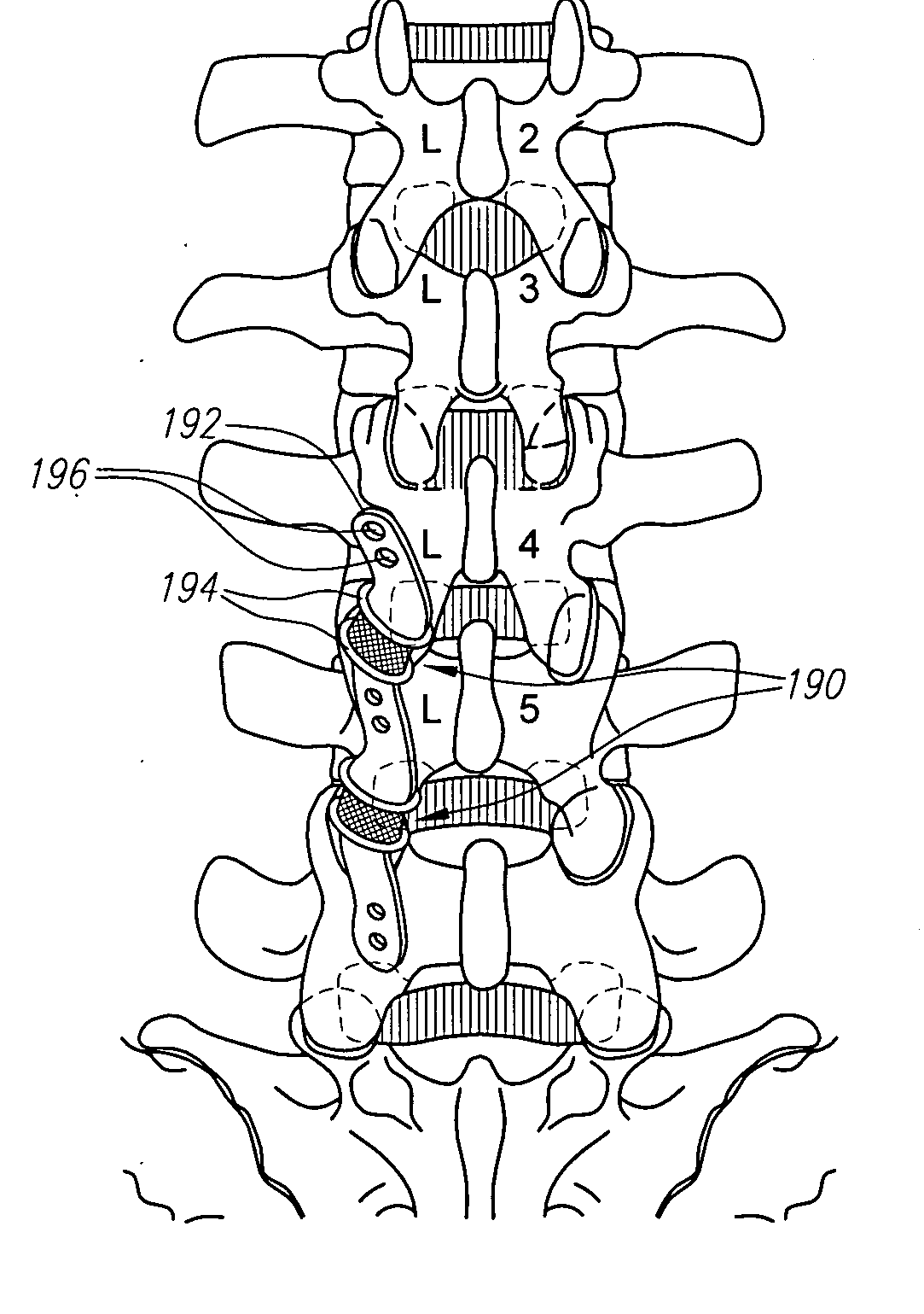
[0012] In a second aspect, devices, systems and methods for facet joint augmentation and replacement are provided. The devices and systems are intended to stabilize the spine and to increase the foramenal space to thereby reduce the likelihood of nerve root impingement. In a first embodiment, the stabilization and increase of foramenal space is accomplished by inserting a stabilizing member into the facet joint to restore the intra-foramenal distance. The stabilizing member comprises a structure that provides shock absorbance, cushioning, and support to the facet joint. In several embodiments, the stabilizing member comprises an encapsulated cushion. In other embodiments, the stabilizing member comprises a structure having a pair of endplates separated by a resilient core member.
[0016] In a fifth aspect, several dynamic stabilization devices are described. Each of the dynamic stabilization devices is intended to provide a combination of stabilizing forces to one or more spinal units to thereby assist in bearing and transferring loads. In a first embodiment, a dynamic stabilization device includes a posterior spacer member that is located generally between a pair of adjacent vertebral bodies on the posterior side of the spine. The posterior spacer is preferably formed of a generally compliant material and functions to maintain spacing between the pair of adjacent vertebral bodies while allowing relative motion between the vertebral bodies. In a preferred form, the posterior spacer is generally in the form of a short cylinder, having a central through-hole to allow passage of one or more restrictor bands, which are described more fully below. The spacer may take other shapes or forms, however, depending upon the size and shape of the spinal treatment site. The dynamic stabilization device also includes one or more restrictor bands, each of which preferably comprises a loop formed of an elastic material. The restrictor band(s) each have a size and shape adapted to be attached to the spinous processes extending from the posterior of the adjacent vertebral bodies, or to be attached by an appropriate attachment mechanism to the lamina of the adjacent bodies. Once linked to the posterior of the spine, the bands provide both stability and compliance. The performance properties of the bands are able to be varied by choice of materials, size of the bands, and by the routing of the restrictor band(s) between the adjacent vertebral bodies. For example, restrictor bands that are oriented more vertically than diagonally will provide greater resistance to flexion of the spine, whereas the more diagonal orientation will provide additional resistance to torsional movements.
[0018] In still other embodiments, a spinal stabilization device is provided that is capable of transferring reactions from one spinal segment to an adjacent segment. In this manner, the spinal stabilization device transfers loads and reactions in the same manner as is done by the natural spinal segments operating properly. The spinal stabilization device includes at least one fixation member associated with each vertebral body, and a linkage member extending between each pair of superior and inferior fixation members. The fixation members each allow for rotation of the linkage members, thereby providing the ability for one vertebral segment to be loaded (or unloaded), either in compression or torsion, based upon the activity being undergone at an adjacent vertebral segment.
[0019] In still other embodiments, a dynamic stabilization device includes a combination of an interspinous stabilization member and one or more pedicle based stabilization members. In a preferred form, the one or more pedicle based stabilization members function by biasing the pair of adjacent vertebral bodies apart, while the interspinous stabilization member functions by biasing together the spinous processes of the adjacent pair of vertebral bodies. The combined action of the interspinous member and the pedicle based member(s) is to create a moment that relieves pressure from the disc.
[0022] In yet other embodiments, a dynamic stabilization device is provided and includes a fill-type adjustment mechanism. The device includes a superior attachment member that is preferably attached to the spinous process of a superior vertebral body, an inferior attachment member that is preferably attached to the spinous process of an inferior vertebral body, and a stabilization member that extends between and interconnects the superior and inferior attachment members. The attachment members may include screws, or other suitable attachment mechanisms. Interposed between at least one of the attachment members and the stabilization member is a pot. As the pot is filled, such as by injecting a biocompatible material such as bone cement containing polymethylmethacrylate (PMMA), the added volume occupied in the pot decreases the operating length of the stabilization member, thereby also changing the performance characteristics of a given stabilization member. Thus, adding material to the pot provides the ability to adjust the device post-operatively. Preferably, the post-operative adjustment may be done percutaneously.

Problems solved by technology

Disorders of the spine comprise some of the costliest and most debilitating health problems facing the populations of the United States and the rest of the world, costing billions of dollars each year.
Moreover, as these populations continue to age, the incidence of spinal disorders will continue to grow.

Method used


Image

  • Spinal stabilization systems and methods
  • Spinal stabilization systems and methods
  • Spinal stabilization systems and methods

Examples


Embodiment Construction

[0047] Before the present invention is described, it is to be understood that this invention is not limited to particular embodiments described, as such may, of course, vary. It is also to be understood that the terminology used herein is for the purpose of describing particular embodiments only, and is not intended to be limiting, since the scope of the present invention will be limited only by the appended claims.

[0048] Where a range of values is provided, it is understood that each intervening value, to at least the tenth of the unit of the lower limit unless the context clearly dictates otherwise, between the upper and lower limit of that range and any other stated or intervening value in that stated range is encompassed within the invention. The upper and lower limits of these smaller ranges may independently be included in the smaller ranges is also encompassed within the invention, subject to any specifically excluded limit in the stated range. Where the stated range include...


PUM


Abstract

Spinal stabilization devices, systems, and methods are described. In a first aspect, a foramenal spacer includes a rigid member adapted to maintain the integrity of the foramenal space. In a second aspect, facet joint stabilizing members and prosthetic facet joints are provided to augment or replace the native facet joint. In a third aspect, lateral spinal stabilization systems are adapted to be attached to the lateral surfaces of adjacent vertebral bodies. In a fourth aspect, anterior spinal stabilization systems are adapted to be attached to the anterior surfaces of adjacent vertebral bodies. In a fifth aspect, several embodiments of dynamic spinal stabilization devices and systems are described. Each of the foregoing devices, systems, and methods is suitable for use independently, in combination with other devices, systems, and methods described herein, and / or in combination with prosthetic intervertebral discs known in the art.

Description

BACKGROUND OF THE INVENTION [0001] The spine is comprised of twenty-four vertebrae that are stacked one upon the other to form the spinal column. The spine provides strength and support to allow the body to stand and to provide flexibility and motion. A Section of each vertebrae includes a passageway that provides passage of the spinal cord through the spinal column. The spine thereby encases and protects the spinal cord. The spinal cord also includes thirty-one pairs of nerve roots that branch from either side of the spinal cord, extending through spaces between the vertebrae known as the neural foramen. [0002] An intervertebral disc is located between each pair of-vertebrae. The disc is composed of three component structures: (1) the nucleus pulposus; (2) the annulus fibrosus; and (3) the vertebral endplates. The disc serves several purposes, including absorbing shock, relieving friction, and handling pressure exerted between the superior and inferior vertebral bodies associated w...

Claims


Application Information

Patent Timeline
Patent Type & Authority Applications(United States)
IPC IPC(8): A61F2/30
CPCA61B17/7064A61B17/7071A61B2017/00867A61F2/4405A61F2/442A61F2002/30563A61F2002/30578A61F2002/4495
Inventor GITTINGS, DARIN C.REO, MICHAEL L.ROBINSON, JANINE C.
Owner SPINAL KINETICS
Why Eureka
Try Eureka