A winding machine for tin phosphor bronze strip and production process using the winding machine

A technology of tin-phosphorus bronze strip and winding machine, which is applied in the directions of winding strips, thin material processing, transportation and packaging, etc., and can solve the problems of high disassembly and operation pressure, large individual, single function, etc.

Active Publication Date: 2021-11-09
鑫谷和金属(无锡)有限公司 +1
View PDF8 Cites 0 Cited by
  • Summary
  • Abstract
  • Description
  • Claims
  • Application Information

AI Technical Summary

Problems solved by technology

[0003] This kind of winder has a simple overall structure, a single function, a large body and high pressure to operate or disassemble, resulting in high pressure to disassemble and operate when manipulating it.

Method used


Image

  • A winding machine for tin phosphor bronze strip and production process using the winding machine
  • A winding machine for tin phosphor bronze strip and production process using the winding machine
  • A winding machine for tin phosphor bronze strip and production process using the winding machine

Examples


Embodiment 1

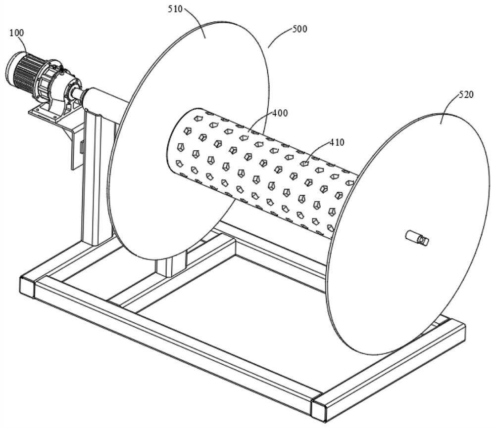
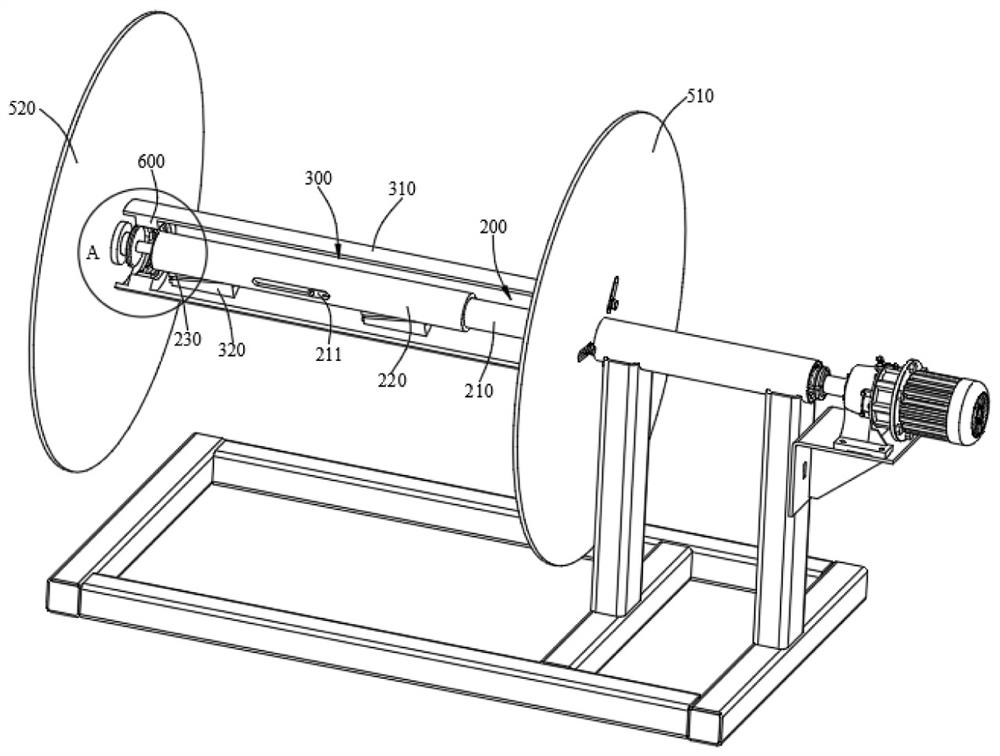
[0057] Such as Figures 1 to 9As described above, the embodiment of the present invention provides a winding machine for tin phosphor bronze strips, including: a driving motor 100, the end of the output shaft of the driving motor 100 is fixed with a driving part 200; several outer support parts 300, the The outer support part 300 is arranged around the driving part 200, and several of the outer support parts 300 are distributed in a ring shape; the outer sleeve 400 has a mesh 410 in the circumferential direction of the outer sleeve 400, and the outer sleeve 400 sets Set on the annular body formed by several of the outer support parts 300; the block part 500, the block part 500 includes the first block 510 fixed on one side of the several outer support parts 300 respectively and the The second blocking piece 520 on the other side of the outer support part 300 ; several clamping parts 600 , each clamping part 600 is located in one of the outer support parts 300 . Wherein the dr...

Embodiment 2

[0078] The present invention also provides a production process using the above winder, including, S1, setting the outer sleeve 400 outside the plurality of outer support parts 300; S2, driving the driving motor 100 to drive The driving part 200 rotates to wind the tin phosphor bronze strip on the outer sleeve 400 and form a single-layer full coverage on the outer wall of the outer sleeve 400; S3, insert the second blocking piece 520 on several Inside the outer support part 300; S4, drive the driving part 200 to drive several of the outer support parts 300 to expand outward to tighten the outer sleeve 400 and clamp the second blocking piece 520; S5. Continue to drive the drive motor until the multi-layers are fully wound.

[0079] In addition, the production process of the winding machine further includes S6, feeding cooling gas into the inlet 523 .

[0080] The production process using the winding machine has the characteristics of fast winding process and good winding effec...


PUM


Abstract

The invention relates to a winding machine for tin-phosphorus bronze strips and a production process using the winding machine. The winding machine for tin-phosphorus bronze strips comprises: a driving part fixed at the end of an output shaft of a driving motor; The part surrounds the driving part, and several outer support parts are distributed in a ring shape; the outer sleeve has mesh holes in the circumferential direction, and the outer sleeve is sleeved on the annular body formed by several outer support parts; The first blocking piece on one side of the support part and the second blocking piece arranged on the other side of the several outer support parts; each clamping part is located in one outer support part. This kind of winder for tin phosphor bronze strip, through the work of the driving motor, drives the driving part to rotate to realize the winding effect of the tin phosphor bronze strip, and realizes the clamping of the outer sleeve and adapting to different thickness requirements through the outer support part The outer sleeve of the outer sleeve, through the setting of the clamping part, triggers the clamping part synchronously when the driving part stretches the outer support part, so as to realize the fixing effect of the clamping part on the second blocking piece.

Description

technical field [0001] The invention relates to a winder, in particular to a winder for a tin phosphor bronze strip and a production process using the winder. Background technique [0002] The winder of the tin phosphor bronze strip in the prior art can only achieve a simple winding effect generally, that is, the worker winds the processed tin phosphor bronze strip into a roll and then stores it as a whole. [0003] This kind of winder has a simple overall structure, a single function, a large body and high pressure to operate or disassemble, resulting in high pressure for people to disassemble and operate when operating. [0004] Therefore, it is necessary to provide a winding machine with various structures and functions and simple operation. Contents of the invention [0005] The object of the present invention is to provide a winding machine for tin phosphor bronze strips to solve the above problems. [0006] In order to achieve the above object, an embodiment of the...

Claims


Application Information

Patent Timeline
Patent Type & Authority Patents(China)
IPC IPC(8): B65H18/02B65H18/10B65H75/24B65H75/14
CPCB65H18/026B65H18/10B65H75/248B65H75/14B65H2701/1133B65H2701/173
Inventor 王小龙朱文斌陈军王耀张磊
Owner 鑫谷和金属(无锡)有限公司
Why Eureka
Try Eureka