Turnover type solar LED underground lamp

An LED underground lamp, solar energy technology, applied in the loss prevention measures of lighting devices, cooling/heating devices of lighting devices, lighting and heating equipment, etc. Effect

Active Publication Date: 2020-03-17
JIANGSU YAMING LIGHTING
View PDF13 Cites 5 Cited by
  • Summary
  • Abstract
  • Description
  • Claims
  • Application Information

AI Technical Summary

Problems solved by technology

[0005] The purpose of the present invention is to solve the problem of low power generation of photovoltaic panels caused by the unreasonable arrangement of the ab

Method used


Image

  • Turnover type solar LED underground lamp
  • Turnover type solar LED underground lamp
  • Turnover type solar LED underground lamp

Examples


Embodiment 1

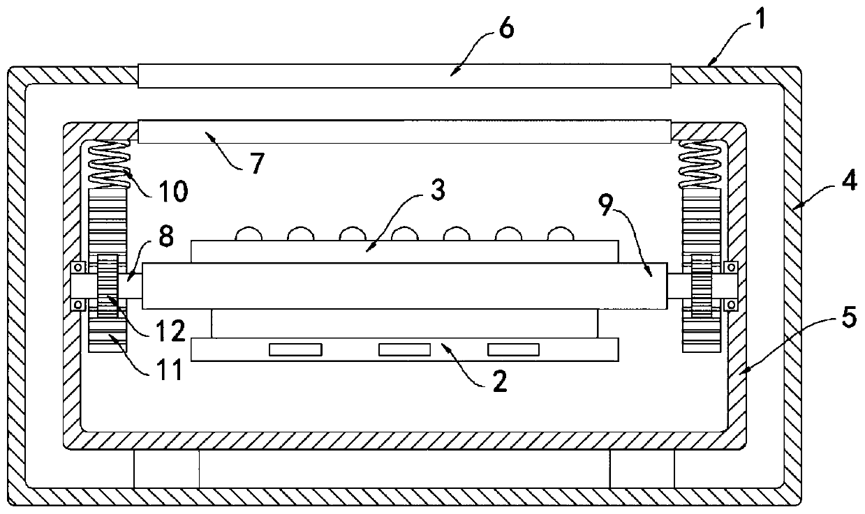
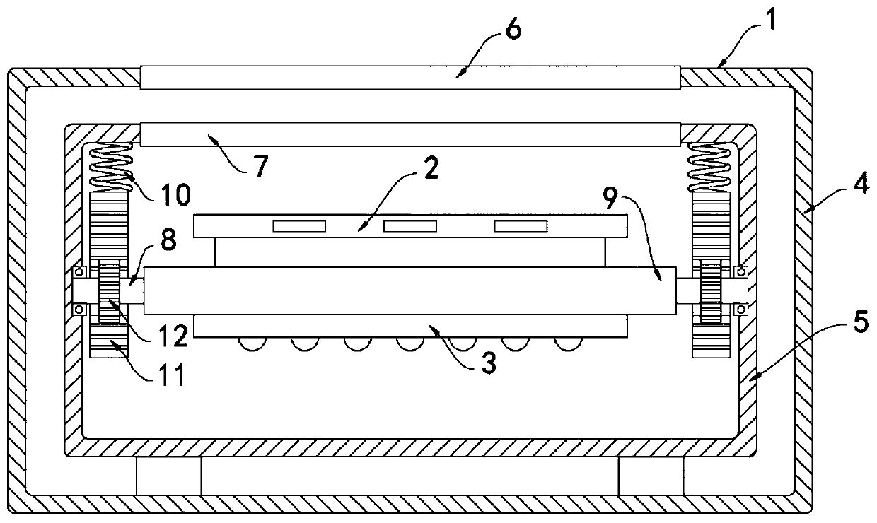
[0020] like Figure 1-2 As shown, a flip-type solar LED underground lamp includes a buried box 1, a photovoltaic panel 2 and an LED light group 3 are arranged in the buried box 1, and the buried box 1 includes an outer casing 4 and an inner casing 5. The outer casing The body 4 is sleeved outside the inner casing 5, the upper ends of the outer casing 4 and the inner casing 5 are both openly arranged, the upper end of the outer casing 4 is fixedly connected with an upper cover plate 6, and the upper end of the inner casing 5 is fixedly connected with a lower cover plate 7. Both the upper cover plate 6 and the lower cover plate 7 are transparent plates, the inner casing 5 and the outer casing 4 are filled with a refracting liquid, the refracting liquid is water, and the inner side wall of the inner casing 5 is rotatably connected with a horizontally arranged The rotating shaft 8, specifically, the rotating shaft 8 is rotatably connected with the inner side wall of the inner casi...

Embodiment 2

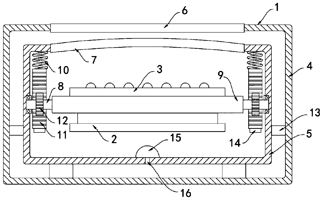
[0026] like Figure 3-4 As shown, the difference between this embodiment and Embodiment 1 is that the lower cover plate 7 is a flexible plate, a sealing ring 13 is slidably and sealedly connected in the cavity formed between the inner casing 5 and the outer casing 4, and two teeth A permanent magnet block 14 is fixedly connected to the lower end of the strip 11 close to the sealing ring 13. The sealing ring 13 is made of magnetic material and attracts the permanent magnet block 14 in opposite poles. It should be noted that the bottom surface of the inner casing 5 is fixedly connected with a storage Liquid bag 15, the liquid storage bag 15 is made of elastic rubber material, the lower end of the liquid storage bag 15 is fixedly connected with the infusion tube 16, the lower end of the infusion tube 16 is arranged through the bottom surface of the inner casing 5, and the sealing ring 13 is in the permanent magnet block 14. The refracting fluid under the sealing ring 13 can be mo...


PUM


Abstract

The invention belongs to the field of LED lamps, in particular to a turnover type solar LED underground lamp including a buried box, a photovoltaic panel and an LED lamp set are arranged in the buriedbox. The buried box comprises an outer shell and an inner shell. The inner shell is sleeved with the outer shell. The upper end of the outer shell and the upper end of the inner shell are both provided with openings. The upper end of the outer shell is fixedly connected with an upper cover plate. The upper end of the inner shell is fixedly connected with a lower cover plate; the upper cover plateand the lower cover plate are both transparent plates, the space between the inner shell and the outer shell is filled with refraction liquid, the inner side wall of the inner shell is rotationally connected with a horizontally-arranged rotating shaft, a horizontally-arranged overturning plate is arranged in the inner shell, and the rotating shaft penetrates through the overturning plate and is fixedly connected with the overturning plate. The underground lamp is reasonable in structure, the positions of the photovoltaic panel and the LED lamp set can be freely switched, the photovoltaic panel and the LED lamp set do not interfere with each other in the working process, the internal space of the buried box is effectively utilized, and the luminous quantity of the photovoltaic panel and the lighting effect of the LED lamp set are guaranteed.

Description

technical field [0001] The invention belongs to the field of LED lamps, in particular to a flip-type solar LED underground lamp. Background technique [0002] LED underground lights are widely used in green belts, parks, lawns, courtyard lighting, pedestrian streets, parking lots, building main body decoration bridges, track lighting, etc. They are mainly buried below the ground and play a role in lighting and decoration. [0003] Most of the existing solar LED underground lights have the problem of unreasonable arrangement of internal components. Since the photovoltaic panels and LED light groups need to be installed face up, the photovoltaic panels and LED light groups can only be set on the same plane. In order to ensure the power generation efficiency of the photovoltaic panels and the lighting effect of the LED lamp group, the internal space of the underground lamp is limited, and the size of the upper cover glass plate is certain, resulting in a small space for the lay...

Claims


Application Information

Patent Timeline
IPC IPC(8): F21S9/03F21V19/00F21V15/01F21V31/00F21V5/04F21V29/56F21Y115/10
CPCF21S9/035F21V5/04F21V15/01F21V19/001F21V31/005F21V29/56F21Y2115/10
Inventor 朱宗一张飞航
Owner JIANGSU YAMING LIGHTING
Why Eureka
Try Eureka