Connecting structure for electronic wristband based on inlaying limiting

A connection structure and electronic wristband technology, applied in the direction of bracelets, applications, watch straps, etc., can solve the problems of complicated adjustment operation of the strap length, inability to fully contact the wrist, and reduced accuracy of heart rate measurement, so as to achieve internal flatness and avoid Shaking, the effect of improving ductility

Active Publication Date: 2020-03-24
深圳微视科技发展有限公司
View PDF7 Cites 2 Cited by
  • Summary
  • Abstract
  • Description
  • Claims
  • Application Information

AI Technical Summary

Problems solved by technology

[0003] The current electronic wristbands are all worn through the strap, but the traditional strap has the following defects when connected: the electronic wristband will also be worn during exercise, and the traditional strap has poor perspiration ability; When the strap is worn, there will be a bulge on the inside, which will cause discomfort to the wrist; the adjustment of the length of the traditional strap is more complicated, and it cannot fully contact the wrist, and it is easy to shake during exercise; and the electronic bracelet also has a The function is to measure the heart rate, and because the contact area between the traditional watch strap and the wrist is small, the general heart rate sensor chip will be installed inside the watch movement, which not only occupies the area of ​​the watch movement, but also the watch movement is located at the wrist on the back of the hand. However, the blood flow and beating of the blood vessels on the inner side of the wrist are more obvious, which reduces the accuracy of heart rate measurement.

Method used


Image

  • Connecting structure for electronic wristband based on inlaying limiting
  • Connecting structure for electronic wristband based on inlaying limiting
  • Connecting structure for electronic wristband based on inlaying limiting

Examples


Embodiment Construction

[0031] The following will clearly and completely describe the technical solutions in the embodiments of the present invention with reference to the accompanying drawings in the embodiments of the present invention. Obviously, the described embodiments are only some, not all, embodiments of the present invention. Based on the embodiments of the present invention, all other embodiments obtained by persons of ordinary skill in the art without making creative efforts belong to the protection scope of the present invention.

[0032] The embodiment of the connection structure for the electronic wristband based on the mosaic limit is as follows:

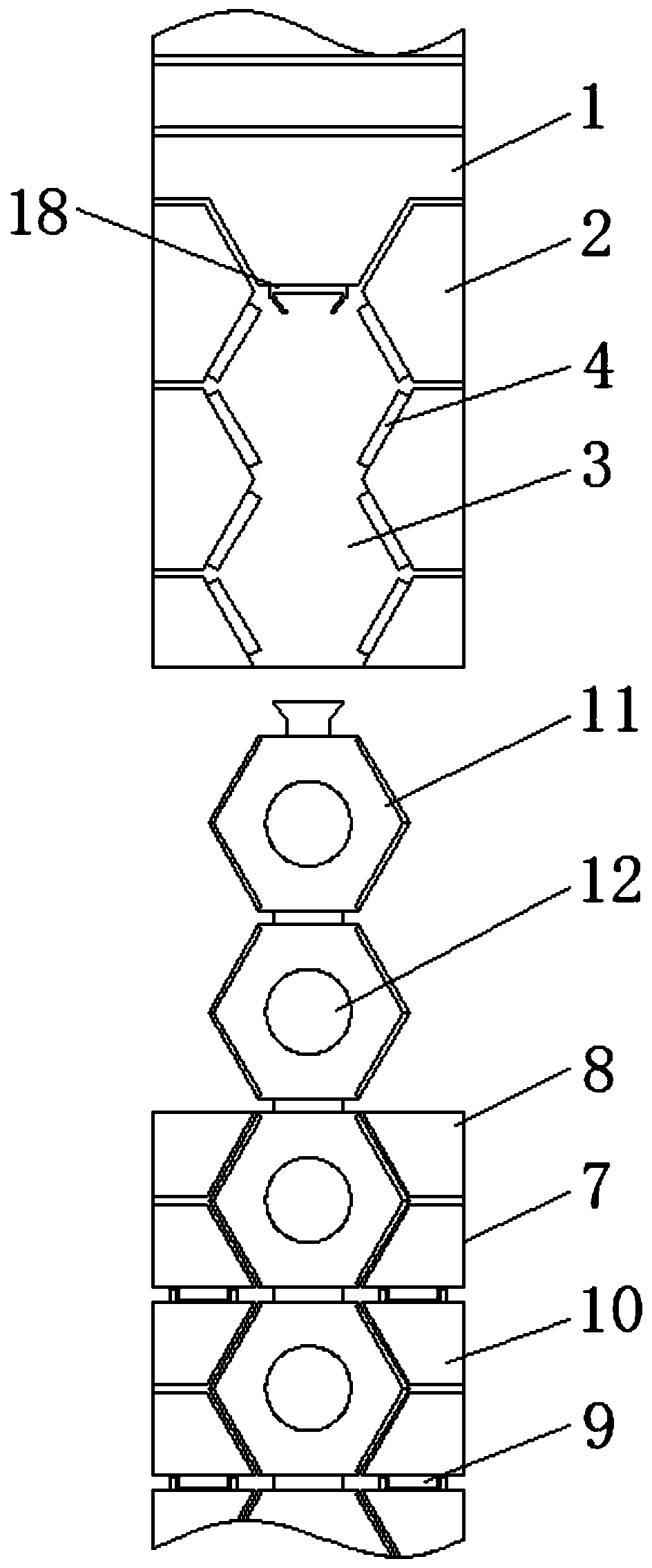
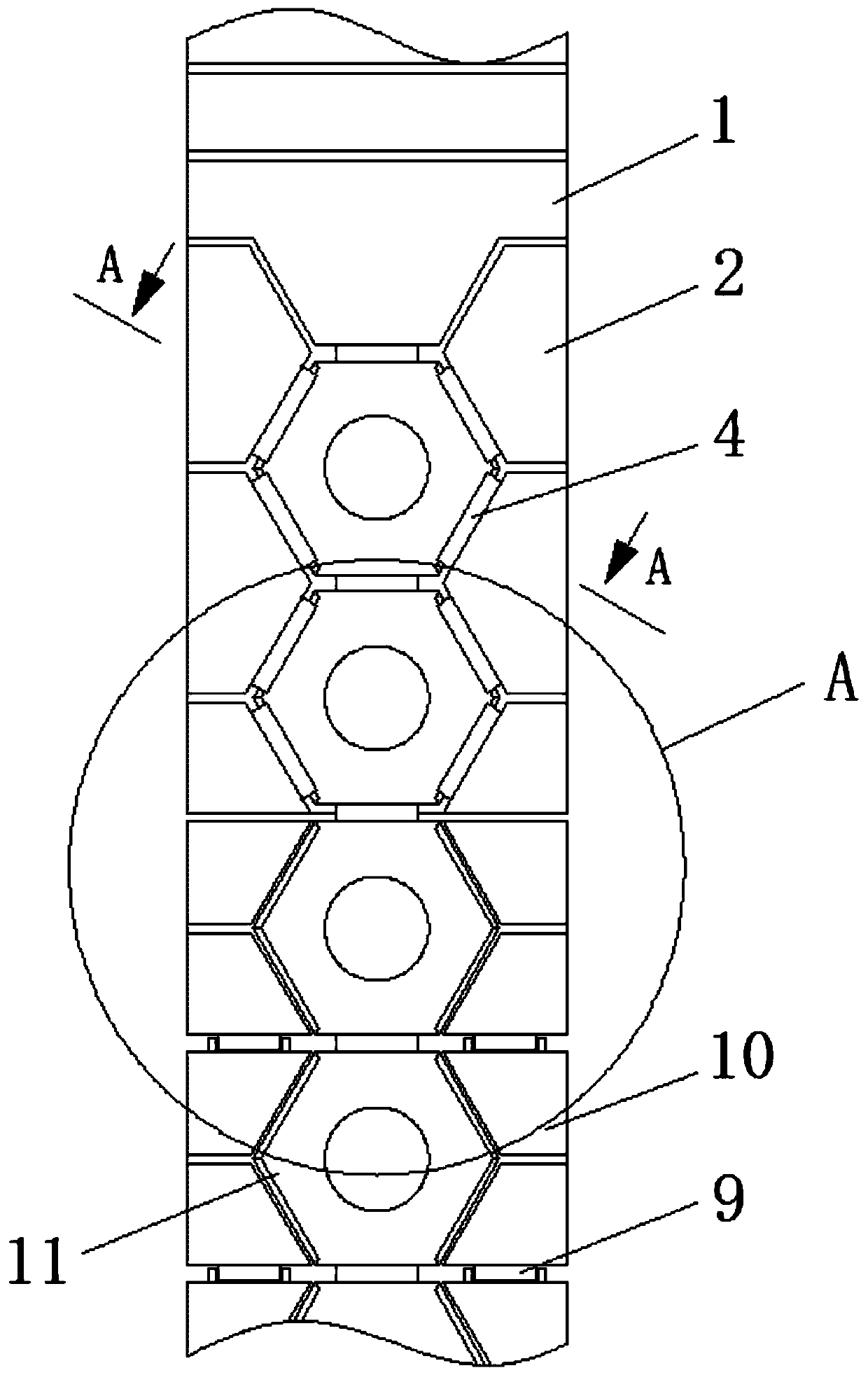
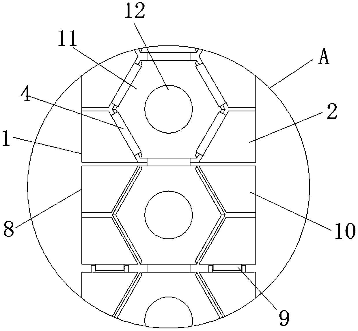
[0033] see Figure 1-8 , a connection structure for an electronic wristband based on inlaid limit, including a left watch strap 1, a first rhombus block 2, a hexagonal groove 3, a limit block 4, a slider 5, a spring 6, a right watch strap 7, a rectangular Block 8, hinge 9, second diamond block 10, regular hexagonal block 11, induction chip...


PUM


Abstract

The invention provides a connecting structure for an electronic wristband based on inlaying limiting, and relates to the technical field of electronic products. The connecting structure comprises a left watchband, first rhombus blocks are fixedly mounted on the inner side of the end, away from a watch movement, of the left watchband, hexagonal grooves are formed between the first rhombus blocks, limiting blocks are slidably connected to the sides, facing the hexagonal grooves, of the first rhombus blocks, and sliding blocks are fixedly mounted at the bottom ends of the limiting blocks. The connecting structure for an electronic wristband based on inlaying limiting is convenient to worn and has an inboard flat, avoids discomfort to the wrist, improves the ductility and sweat absorption effect of the watchband, can be suitable for people with different wrist thicknesses, guarantees the mutual attachment of the watchband and the wrist, avoids the shaking of the wristband, can sense the heart rate change of the inner side of the wrist, reduces the size of the watch movement, and improves the heart rate measurement precision.

Description

technical field [0001] The invention relates to the technical field of electronic products, in particular to a connection structure for an electronic wristband based on an inlay limit. Background technique [0002] Electronic products are related products based on electric energy. Because the early products were mainly based on electronic tubes, they were named electronic products, and electronic bracelets are one of them. They are also called smart sports bracelets. Today, with the rapid development of science and technology, an innovatively designed product has various modes such as supporting activities, exercising, and sleeping during use. It can record personal nutritional status, and has functions such as smart alarm clock and health reminder. [0003] The current electronic wristbands are all worn through the strap, but the traditional strap has the following defects when connected: the electronic wristband will also be worn during exercise, and the traditional strap ...

Claims


Application Information

Patent Timeline
Patent Type & Authority Applications(China)
IPC IPC(8): A44C5/10
CPCA44C5/107
Inventor 史文献
Owner 深圳微视科技发展有限公司
Why Eureka
Try Eureka