
Explosion-proof device of vacuum heat insulation container

An explosion-proof device and vacuum insulation technology, applied in pressure vessels, container filling methods, container discharge methods, etc., can solve the problems of low safety, lost workers, short vacuum life maintenance time, etc., to improve the sealing effect and meet the needs of use. Demand, design reasonable effect

Pending Publication Date: 2020-03-24
张腾
View PDF0 Cites 0 Cited by
  • Summary
  • Abstract
  • Description
  • Claims
  • Application Information

AI Technical Summary

Problems solved by technology

[0002] Since 2000, with the development of industry, more and more low-temperature vacuum insulation containers have been circulated in the market, and a series of potential safety hazards of vacuum interlayers and short vacuum life maintenance time have emerged.
[0003] At present, most of the explosion-proof devices for vacuum insulated containers used by most manufacturers in the market do not have the function of shielding and protecting the explosion-proof cover, which makes it easy to injure workers or lose them when the explosion-proof cover breaks out when a high-temperature fault occurs. The safety is low, and most of them do not have the function The explosion-proof cover has the function of automatically moving back and sealing after popping up, and most of them are single-channel sealing, which cannot meet the needs of use. Therefore, we propose a vacuum insulation container explosion-proof device to solve the above problems

Method used


Image

  • Explosion-proof device of vacuum heat insulation container
  • Explosion-proof device of vacuum heat insulation container
  • Explosion-proof device of vacuum heat insulation container

Examples


Embodiment

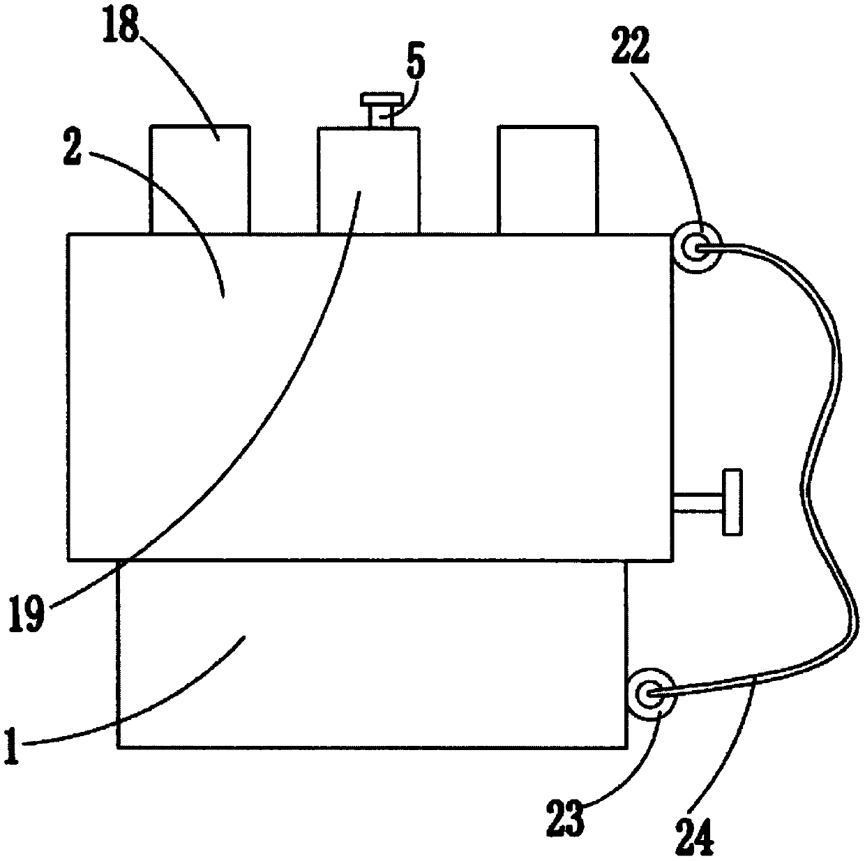
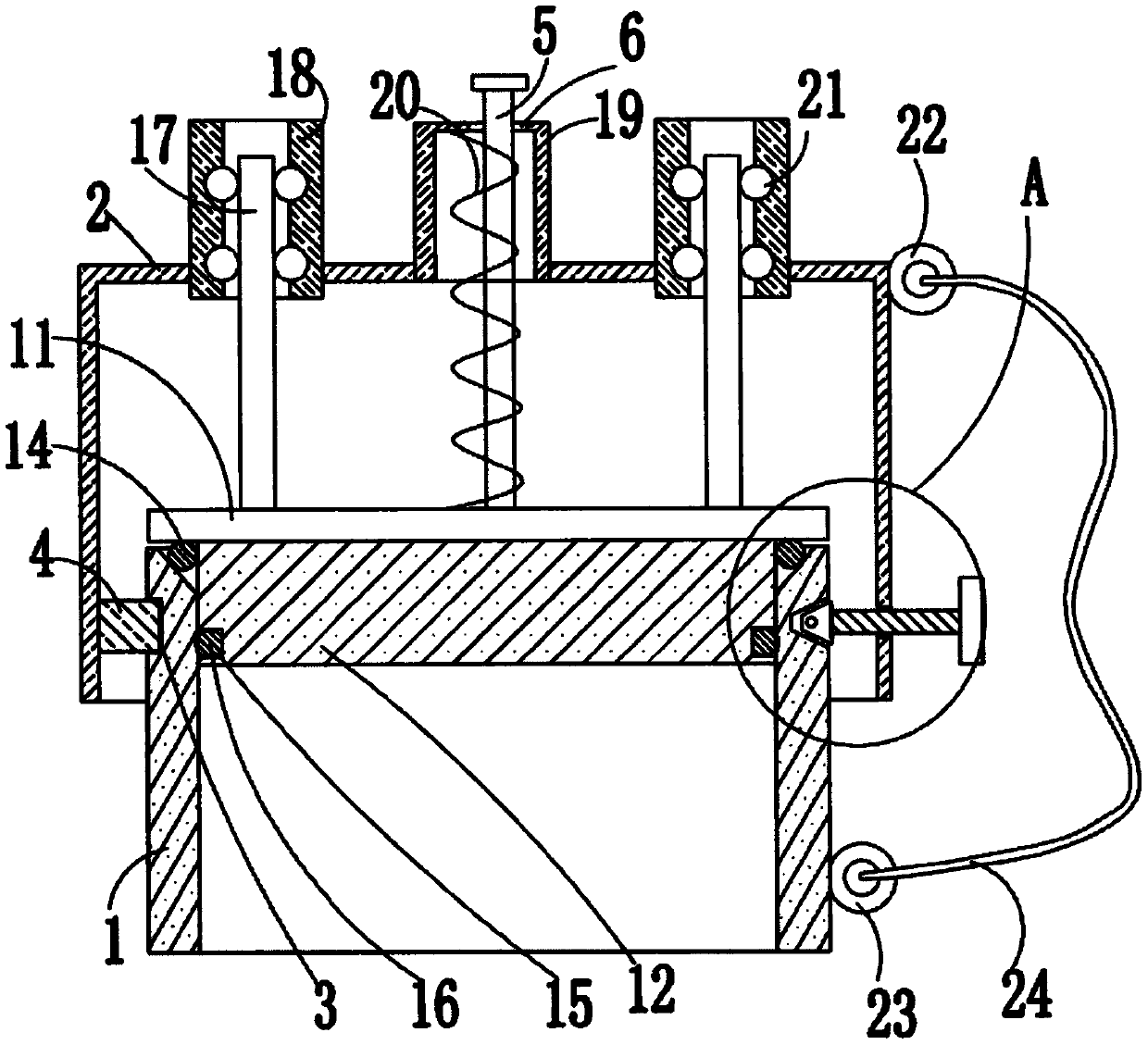
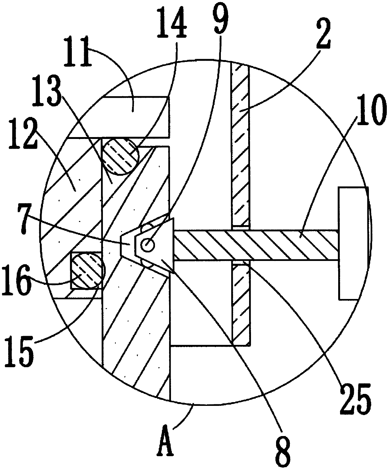
[0025] refer to Figure 1-5 , this embodiment proposes an explosion-proof device for a vacuum heat-insulated container, including an explosion-proof cylinder 1, a block 12 is set in a movable seal in the explosion-proof cylinder 1, and the top of the block 12 extends to the top of the explosion-proof cylinder 1 and is fixed. The upper cover 11 is connected, the explosion-proof cylinder 1 is covered with a protective cover 2, the top of one side of the explosion-proof cylinder 1 is provided with a rectangular groove 3, and the inner wall of one side of the protective cover 2 is fixedly connected with a rectangular block 4, a rectangular block 4 Fitted with the rectangular groove 3 movably, the top of the other side of the explosion-proof cylinder 1 is provided with a first frustum-shaped groove 7, and a frustum-shaped block 8 is arranged in the first frustum-shaped groove 7, and the outer side of the frustum-shaped block 8 is annularly embedded. A plurality of first balls 9 are...


PUM


Abstract

The invention discloses an explosion-proof device of a vacuum heat insulation container. The device comprises an explosion-proof cylinder, wherein a plugging block is movably sleeved in the explosion-proof cylinder in a sealing manner, the top of the blocking block extends to the position above the anti-explosion cylinder and is fixedly connected with an upper cover, the explosion-proof cylinder is sleeved with a protective cover, a rectangular groove is formed in the top of one side of the explosion-proof cylinder, a rectangular block is fixedly connected with an inner wall of one side of theprotective cover, the rectangular block and the rectangular groove are movably clamped, a first circular-truncated-cone-shaped groove is formed in the top of the other side of the explosion-proof cylinder, and a circular-truncated-cone-shaped block is arranged in the first circular-truncated-truncated-cone-cone-shaped groove. The device is reasonable in design and is simple in structure and convenient to use, the upper cover can be shielded and protected through the protective cover, workers are prevented from being injured or lost after the upper cover is burst out due to high-temperature faults, safety is high, the function of automatic retreating and blocking after the upper cover and the blocking block are popped up is achieved, the sealing effect can be improved through double sealing, the protective cover can be conveniently and rapidly disassembled for later maintenance, and use requirements are met.

Description

technical field [0001] The invention relates to the field of explosion-proof technology for vacuum heat-insulated containers, in particular to an explosion-proof device for vacuum heat-insulated containers. Background technique [0002] Since 2000, with the development of industry, more and more low-temperature vacuum insulation containers have been circulated in the market, and a series of hidden safety hazards of vacuum interlayers and short vacuum life maintenance time have emerged. [0003] At present, most of the explosion-proof devices for vacuum insulated containers used by most manufacturers in the market do not have the function of shielding and protecting the explosion-proof cover, which makes it easy to injure workers or lose them when the explosion-proof cover breaks out when a high-temperature fault occurs. The safety is low, and most of them do not have the function The explosion-proof cover has the function of automatically moving back and sealing after poppin...

Claims


Application Information

Patent Timeline
IPC IPC(8): F17C13/12F17C1/12
CPCF17C13/123F17C1/12F17C2260/042
Inventor 张腾张鲁军樊卫华
Owner 张腾
Learn More