Mounting structure of ultrasonic flowmeter probe

An installation structure and flowmeter technology, which is applied in the direction of measuring devices, volume measurement, flow measurement/mass flow, etc., can solve the problems of ultrasonic flowmeter measurement data error, affecting ultrasonic flowmeter data measurement, troublesome installation and disassembly, etc. To achieve the effect of improving accuracy

Inactive Publication Date: 2020-03-24
西安西派测控技术有限公司
View PDF3 Cites 2 Cited by
  • Summary
  • Abstract
  • Description
  • Claims
  • Application Information

AI Technical Summary

Problems solved by technology

[0003] In view of this, Chinese Patent No. CN202885879U proposes an installation structure and fixture for ultrasonic flowmeter probes, which has the advantages of simple structure, convenient installation and operation, and wide application range. Chinese Patent No. CN204594513U proposes an installation structure for ultrasonic flowmeter probes Positioning installation device, Chinese Patent No. CN207798172U proposes a probe fixture for a hand-held ultrasonic flowmeter. Most of the probes of the ultrasonic flowmeter are directly fixed on the pipeline during installation, which is troublesome in terms of installation and disassembly. The two probes are installed on the same diameter section. If there is a deviation in the installation, it is easy to cause errors in the measurement data of the ultrasonic flowmeter and affect the data measurement of the ultrasonic flowmeter.

Method used


Image

  • Mounting structure of ultrasonic flowmeter probe
  • Mounting structure of ultrasonic flowmeter probe
  • Mounting structure of ultrasonic flowmeter probe

Examples


Embodiment 1

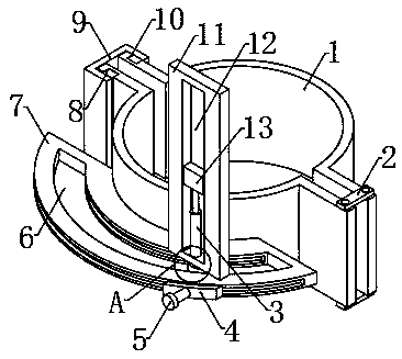
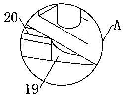
[0021] like figure 1 and image 3 As shown, an installation structure of an ultrasonic flowmeter probe includes two splints 1, one end on both sides of the two splints 1 is respectively connected to the two ends of the two fixed plates 2 through four rotating shafts, and the two splints 1 One end of one side is provided with a first chute 10, and the two sides of the inner walls of the two first chute 10 are respectively slidably connected with the two sides of the two slide plates 8, and one side of the two slide plates 8 is connected with the U-shaped plate 9 respectively. The two sides of the inner wall are fixedly connected, and the two splints 1 are set on the pipeline to be tested, and the slide plate 8 is drawn into the first chute 10, so that the splint 1 is fixed, and the probe body 18 can be fixed on the pipeline to be tested. To facilitate the installation and disassembly of the probe body 18, the middle part of one side of the splint 1 is fixed with an arc-shaped ...

Embodiment 2

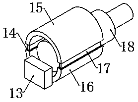
[0023] On the basis of embodiment one, refer to figure 1 and image 3 , the top of the slide bar 19 is fixedly connected to the middle part of the bottom end of the moving plate 11, and the middle part on one side of the moving plate 11 is provided with a third chute 12, and the two sides of the third chute 12 inner wall are connected with the two sides of the second slider 13 respectively. Slidingly connected, the middle part of one side of the second slider 13 is fixedly connected with the middle part of one side of the bottom plate 16, the inner wall of the bottom plate 16 is engaged with the outer wall of the probe body 18, and both sides of the top of the bottom plate 16 are provided with card slots 14. Two clamping grooves 14 are engaged and connected with two clamping plates 17 respectively, and the two clamping plates 17 are respectively fixedly arranged on both sides of the bottom end of the top plate 15, the probe body 18 is placed on the bottom plate 16, and the cla...


PUM


Abstract

The invention discloses a mounting structure of an ultrasonic flowmeter probe. The mounting structure comprises two clamping plates, the two clamping plates are sleeved on a pipeline to be measured; the sliding plate slides into the first sliding groove, therefore, the clamping plates are fixed, the probe body can be fixed on a pipeline to be detected, the probe body is convenient to mount and dismount; the clamping groove is clamped with the clamping plate, therefore, the probe body is fixed on the bottom plate, the probe body can be conveniently protected; the probe body is prevented from being impacted and damaged; sliding a first slider, the first sliding block drives the sliding rod to move; the probe body is driven to move horizontally; the position of the probe body in the horizontal direction is conveniently adjusted; the mechanical telescopic rod moves to drive the second sliding block to vertically move, so that the bottom plate is driven to move, namely the probe body is driven to vertically move, the position of the probe body in the vertical direction is conveniently adjusted, the position of the probe body can be conveniently adjusted, and the accuracy of measurementdata of the ultrasonic flowmeter is conveniently improved.

Description

technical field [0001] The invention relates to an ultrasonic flowmeter, in particular to an installation structure of an ultrasonic flowmeter probe. Background technique [0002] Clamp-on or pipe-type ultrasonic flow meters are based on the principle of "speed difference method" to measure the flow of liquid in a circular tube. It uses advanced multi-pulse technology, signal digital processing technology and error correction technology to make the flow meter more accurate. Adapt to the environment of the industrial site, the measurement is more convenient, economical and accurate, the product has reached the advanced level at home and abroad, and can be widely used in petroleum, chemical industry, metallurgy, electric power, water supply and drainage and other fields. [0003] In view of this, Chinese Patent No. CN202885879U proposes an installation structure and fixture for ultrasonic flowmeter probes, which has the advantages of simple structure, convenient installation a...

Claims


Application Information

Patent Timeline
Patent Type & Authority Applications(China)
IPC IPC(8): G01F15/18G01F15/00G01F1/66
CPCG01F1/66G01F15/00G01F15/18
Inventor 武伟东
Owner 西安西派测控技术有限公司
Why Eureka
Try Eureka