
Camera detection method

A detection method and camera technology, which is applied in the field of camera detection, can solve problems such as the inability to sieve good products and defective products, lack of efficient and reliable camera defective product detection methods, etc.

Inactive Publication Date: 2020-03-24
惠州市旭宝光电科技有限公司
View PDF2 Cites 0 Cited by
  • Summary
  • Abstract
  • Description
  • Claims
  • Application Information

AI Technical Summary

Problems solved by technology

In the camera industry, there is an agreed allowable range for the error value of the camera. For the camera whose error value is within the allowable range, it can be marked as a good product, and for the camera whose error value exceeds the allowable range, it needs to be marked as a defective product, but currently The industry lacks an efficient and reliable camera defect detection method, and cannot quickly and accurately sort good and defective products, which needs to be improved urgently

Method used

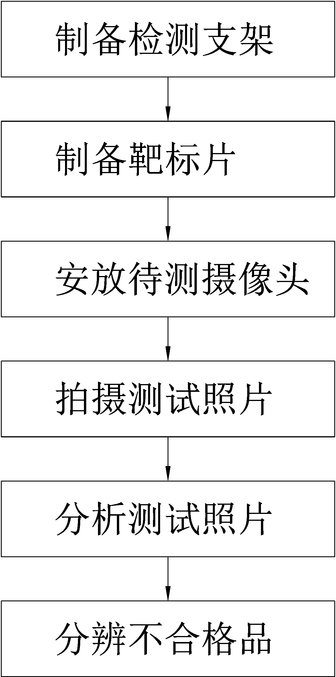
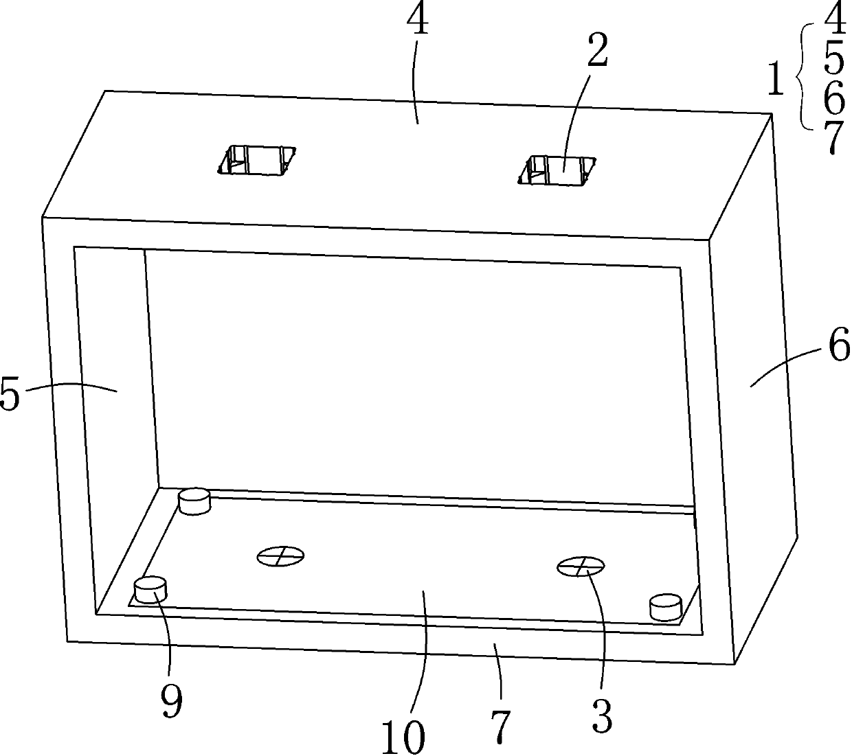
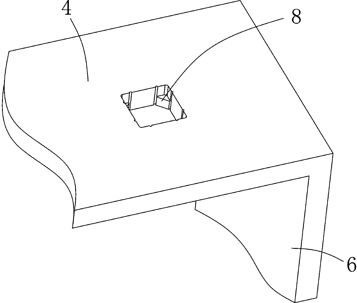

Image

  • Camera detection method
  • Camera detection method
  • Camera detection method

Examples


Embodiment 1

[0027] Please refer to Figure 1-3 , Embodiment 1 of the present invention includes:

[0028] A camera detection method, comprising the steps of:

[0029] Step 1. Prepare the detection bracket. The upper part of the bracket is a fixed position for fixing the camera to be tested, and the lower part of the bracket is a workbench. The camera to be tested fixed at the fixed position can take pictures of the workbench; the detection bracket 1 includes a top plate 4 and a side plate-5 , side plate 2 6 and bottom plate 7; the fixing position is to dig the mounting hole 2 located at the top plate 4, the target 3 faces the mounting hole 2, the lens of the camera placed on the mounting hole 2 faces the target 3, and the mounting hole 2 runs through the top plate 4 , The inner wall of the mounting hole 2 is also provided with a block 8 .

[0030] Step 2. Prepare the target sheet, select the sheet as the target sheet, and draw or paste the target on the surface of the target sheet. The ...

Embodiment 2

[0036] Embodiment 2 of the present invention includes:

[0037] A camera detection method, comprising the steps of:

[0038] Step 1. Prepare the detection bracket. The upper part of the bracket is the fixed position for fixing the camera to be tested, and the lower part of the bracket is the workbench. The camera to be tested fixed at the fixed position can take pictures of the workbench; the detection bracket includes top plate, side plate 1, and side plate Erhe bottom plate; the fixed position is to dig the mounting hole located on the top plate, the target faces the mounting hole, the lens of the camera placed on the mounting hole faces the target, the mounting hole runs through the top plate, and the inner wall of the mounting hole is also provided with a block.

[0039] Step 2. Prepare the target sheet, select the sheet as the target sheet, and draw or paste the target on the surface of the target sheet. The target has an outer circle and a cross-shaped intersection locat...


PUM


Abstract

The invention relates to a camera detection method, which comprises the following steps: step 1, preparing a detection support, the upper part of the support being a fixing position for fixing a camera to be detected, the lower part of the support being a workbench, and the camera to be detected fixed at the fixing position being capable of shooting the workbench; step 2, preparing a target sheet,selecting a sheet-shaped object as the target sheet, and drawing or pasting a target on the surface of the target sheet, the target having an outer circle and a cross-shaped intersection located inside the outer circle; step 3, fixing the target piece to a workbench, wherein the center of a target in the target piece and the central axis of the fixing position are located on the same straight line; step 4, starting a to-be-tested camera, and photographing the workbench by the to-be-tested camera to obtain a photographed picture with a target; and step 5, analyzing the shot picture with the target, measuring the distance between the center of the target and the center of the picture, and recording the distance as an offset value A. The invention provides a camera detection method which canquickly and accurately distinguish defective products in a camera.

Description

technical field [0001] The invention relates to the detection field, in particular to a camera detection method. Background technique [0002] During the production process of the camera, there will inevitably be industrial errors in the installation of the lens. In the camera industry, there is an agreed allowable range for the error value of the camera. For the camera whose error value is within the allowable range, it can be marked as a good product, and for the camera whose error value exceeds the allowable range, it needs to be marked as a defective product, but currently The industry lacks an efficient and reliable camera defect detection method, and cannot quickly and accurately sort good and defective products, which needs to be improved urgently. Contents of the invention [0003] In view of this, the present invention provides a camera detection method, which can quickly and accurately distinguish defective products in the camera. [0004] The object of the pre...

Claims


Application Information

Patent Timeline
IPC IPC(8): G01M11/02G01M11/04
CPCG01M11/0214G01M11/0257G01M11/04
Inventor 吴辉杨永涛杨平原黎雄广
Owner 惠州市旭宝光电科技有限公司
Learn More