Gravity electromagnetic circuit breaker

A circuit breaker, electromagnetic technology, applied in the direction of circuit breaker components, circuits, circuit breaker contacts, etc., can solve the problems of easy loss of magnetism, device failure, etc., to avoid device failure, reduce impact force, reduce high temperature Harmful effect

Inactive Publication Date: 2020-03-24
HUBEI UNIV OF TECH
View PDF1 Cites 0 Cited by
  • Summary
  • Abstract
  • Description
  • Claims
  • Application Information

AI Technical Summary

Problems solved by technology

A circuit breaker in the above-mentioned patent has the following disadvantages: the magnet easily loses its magnetism, causing the device to fail

Method used


Image

  • Gravity electromagnetic circuit breaker
  • Gravity electromagnetic circuit breaker
  • Gravity electromagnetic circuit breaker

Examples


Embodiment 1

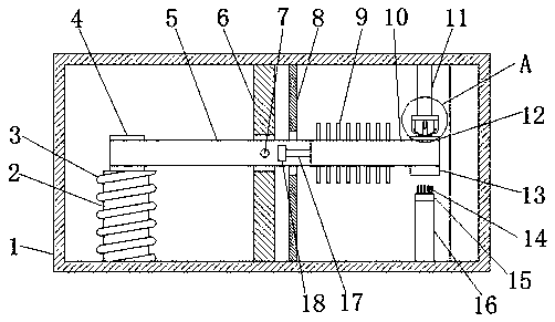
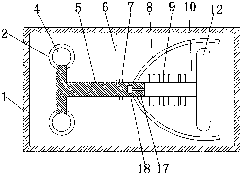
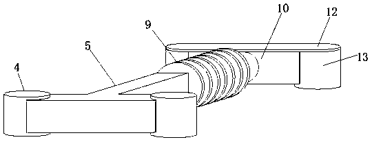
[0028] refer to Figure 1-4 , a gravity electromagnetic circuit breaker, comprising a box body 1, a baffle plate 6 bonded to the middle of the box body 1, a first through hole is opened in the middle of the baffle plate 6, and the baffle plate 6 passes through the rotating shaft 7 at the first through hole An insulator 5 is rotatably connected, iron blocks 4 are bonded to both sides of one end of the insulator 5, an iron core 2 is bonded to the bottom of the box body 1, a coil 3 is set on the outside of the iron core 2, and a coil 3 is set on the other end of the insulator 5. There is a heat conduction column 10, and both sides of one end of the heat conduction column 10 are provided with counterweights 13, the top of the two counterweights 13 is bonded with the same first conductor 12, and the top of the box body 1 is bonded with two supports Column 11, the bottom ends of the two supporting columns 11 are bonded with second conductors 19, and the bottom ends of the two second...

Embodiment 2

[0040] refer to Figure 5 , a gravity electromagnetic relay. Compared with Embodiment 1, in this embodiment, in order to increase the stability of the device and prevent the insulator 5 from rotating freely when the device is not in use, the top of the box body 1 is rotatably connected with a rotating body 28. The rotating body One end of the bottom end of 28 is provided with magnet 27, and the top inner wall of box body 1 is provided with second through hole, and box body 1 is provided with iron column 26 at the second through hole place, and the top of insulator 5 is bonded with connecting column 24, connects The top of post 24 is bonded with iron sheet 25, and rotating rotating body 28 makes rotating body 28 drive magnet 27 to come to the top of iron post 26, and iron post 26 can attract iron sheet 25, so that iron sheet 25 rises, and iron sheet 25 The insulator 5 is rotated and fixed to prevent the insulator 5 from rotating freely.

[0041] During use, when the coil 3 is ...


PUM


Abstract

The invention belongs to the technical field of circuit breakers, in particular to a gravity electromagnetic breaker. In order to solve the problem that a permanent magnet of a magnetic circuit breaker is easy to lose magnetism and cause failure, the circuit breaker comprises a box body, a baffle plate is adhered to the middle part of the box body; a first through hole is formed in the middle of the baffle, the baffle is rotationally connected with an insulator through a rotating shaft at the first through hole, iron blocks are bonded to the two sides of one end of the insulator, an iron coreis bonded to the bottom end of the box body, the iron core is sleeved with a coil, a heat conduction column is arranged at the other end of the insulator, and balancing weights are arranged on the twosides of one end of the heat conduction column. When the coil is powered on, the iron block is attracted, the iron block drives the insulator to rotate, the two elastic pieces are connected, the device is closed, and when the coil is powered off, due to the gravity effect, the two elastic pieces are disconnected, the device is disconnected, the gravity effect is utilized, a permanent magnet is replaced, and device faults caused by instability of the permanent magnet are effectively avoided.

Description

technical field [0001] The invention relates to the technical field of circuit breakers, in particular to a gravity electromagnetic circuit breaker. Background technique [0002] A circuit breaker is a common basic electrical component. Existing electromagnetic circuit breakers are closed by permanent magnets. However, permanent magnets tend to lose their magnetism in high-temperature environments or under collision conditions, resulting in failure of the circuit breaker. [0003] After searching, the Chinese patent application number is 201910359057.3, which discloses a circuit breaker, including a housing and a rotating roller that rotates on the housing and is arranged through the housing; one end of the rotating shaft is fixed with a The triangular block abutted by the magnet is provided with two electromagnet assemblies at the upper and lower ends of the magnet respectively, and the upper electromagnet assembly is used to repel the magnet downward. A circuit breaker in...

Claims


Application Information

Patent Timeline
IPC IPC(8): H01H71/24H01H73/04H01H73/18H01H9/52
CPCH01H9/52H01H71/24H01H73/04H01H73/18
Inventor 汪繁荣宋强彭禄王达
Owner HUBEI UNIV OF TECH
Why Eureka
Try Eureka