
Tooth cleaning equipment

A technology for tooth cleaning and equipment, applied in the fields of cleaning teeth, dentistry, medical science, etc., can solve the problems of low efficiency, long time consumption, children with poor compliance, etc., and achieve the effect of easy operation and low manufacturing cost

Active Publication Date: 2020-03-27
XINYI XIYI ADVANCED MATERIALS RES INST OF IND TECH CO LTD
View PDF4 Cites 4 Cited by
  • Summary
  • Abstract
  • Description
  • Claims
  • Application Information

AI Technical Summary

Benefits of technology

This technology allows people with different types or ages to easily remove plaque from their teeth without having them stop doing it themselves again after they have had time. By moving each side's brushing rollers along its way, this process cleans up all parts of your mouth while also making sure there are no hidden areas where debris may get stuck during these steps.

Problems solved by technology

This patented technical problem addressed in this patents relates to improving the efficiency and effectiveness of conventional manual toothbath treatments used during childhood development. Traditional ways require multiple steps such as rinses with water followed by dryings on top of them before being able to effectively remove plaque from their teeth. These techniques have been shown to lead to harmful effects like root canalitis caused by bacteria growth within the tissues around the roots where they were located. To address these issues, there was developed an improved version called electric toothpaste which uses electrical current instead of water but still works well even when trying to achieve better results compared to older versions.

Method used


Image

  • Tooth cleaning equipment
  • Tooth cleaning equipment
  • Tooth cleaning equipment

Examples


Embodiment Construction

[0017] Combine below Figure 1-4 The present invention is described in detail, and for convenience of description, the orientations mentioned below are now stipulated as follows: figure 1 The up, down, left, right, front and back directions of the projection relationship itself are the same.

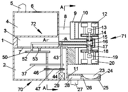
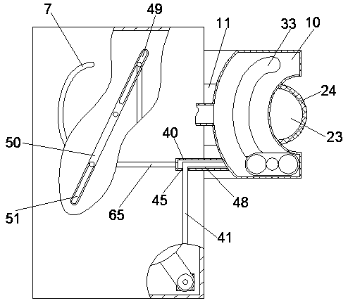
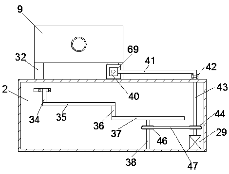
[0018] refer to Figure 1-4 , a tooth cleaning device according to an embodiment of the present invention, comprising a main body 1, a main transmission chamber 2 is arranged in the main body 1, a water storage chamber 4 is arranged on the upper side of the main transmission chamber 2, and a water storage chamber 4 is arranged on the upper side of the main transmission chamber 2. A connecting rod chamber 3 is provided between the transmission chamber 2 and the water storage chamber 4, and the right side wall of the connecting rod chamber 3 communicates with the outside of the main body 1, and the main transmission chamber 2 is provided with a drive for the operation of the present inven...


PUM


Abstract

The invention discloses tooth cleaning equipment. The tooth cleaning equipment comprises a main machine body, wherein a main transmission cavity is formed in the main machine body; a water storage cavity is formed in the upper side of the main transmission cavity; a connecting rod cavity is formed between the main transmission cavity and the water storage cavity; the right side wall of the connecting rod cavity externally communicates with the main machine body; a driving device for driving the tooth cleaning equipment to operate is arranged in the main transmission cavity; the driving devicecomprises an electromotor which is mounted on the lower side wall of the main transmission cavity; and a main transmission shaft which extends upwards to the outside of the main machine body is mounted at the tail end of the upper side of the electromotor. According to the tooth cleaning equipment disclosed by the invention, upper teeth and lower teeth can be brushed through two-sided hair brush wheels II and a hair brush wheel I as well as a hair brush wheel III and two-sided hair brush wheels IIII, and thus, the tooth cleaning equipment is simple and convenient to operate, and is low in manufacturing cost; and through only needing to bite an upper tooth brace and a lower tooth brace, an automatic tooth cleaning effect is realized through rotatable hair brushes, and therefore, convenienceis provided for those people who cannot brush own teeth.

Description


Claims


Application Information

Patent Timeline
Owner XINYI XIYI ADVANCED MATERIALS RES INST OF IND TECH CO LTD
Learn More