Cutter clamping structure of tool changing mechanism

A technology of clamping structure and tool changing mechanism, which can be used in clamping, manufacturing tools, metal processing mechanical parts, etc.

Active Publication Date: 2020-03-27
NEW GIFU ENTERPRISE
View PDF7 Cites 0 Cited by
  • Summary
  • Abstract
  • Description
  • Claims
  • Application Information

AI Technical Summary

Problems solved by technology

However, the above-mentioned tool clamping device mainly fixes the tool by having a clamping section corresponding to the shape of the tool through its two clamping arms. The holding device only fixes the tool clamping through the oblique cone-shaped knife clamping section. As a result, when the tool clamping device is pivoted, centrifugal force is generated due to the swing of the pivot, and the tool is likely to be separated from the clamping arm along the knife clamping section. , so that the tool exchange work cannot be carried out smoothly

Method used


Image

  • Cutter clamping structure of tool changing mechanism
  • Cutter clamping structure of tool changing mechanism
  • Cutter clamping structure of tool changing mechanism

Examples


Embodiment Construction

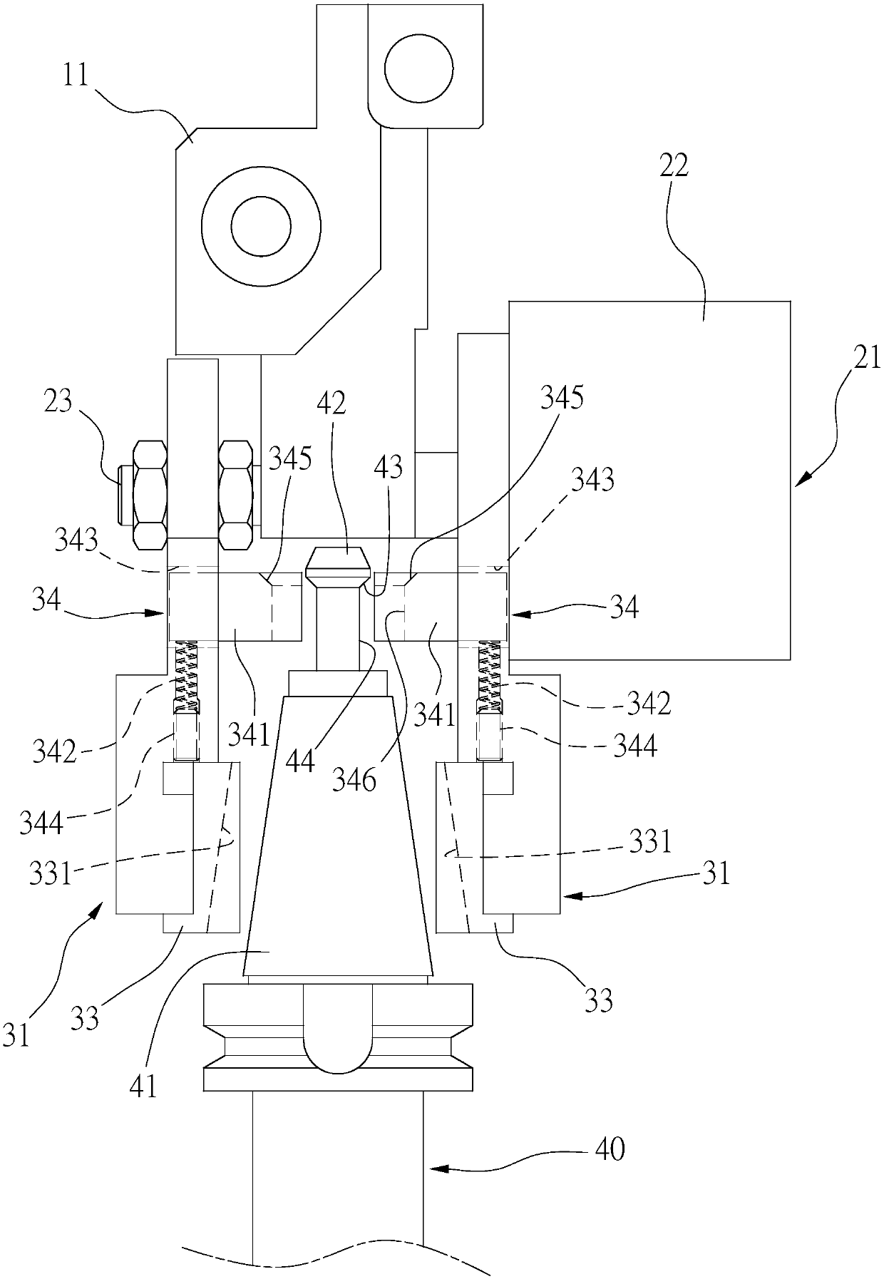
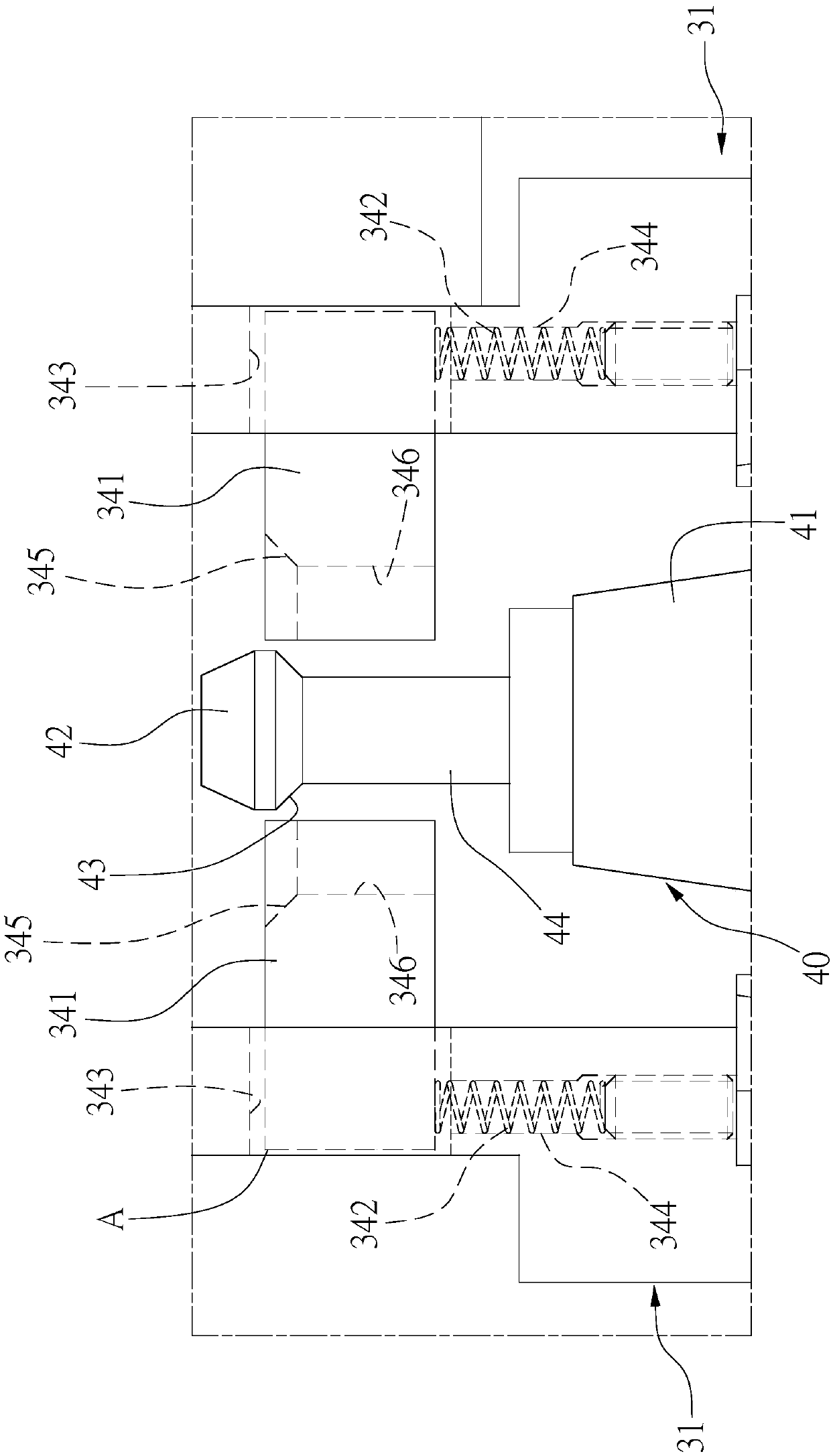
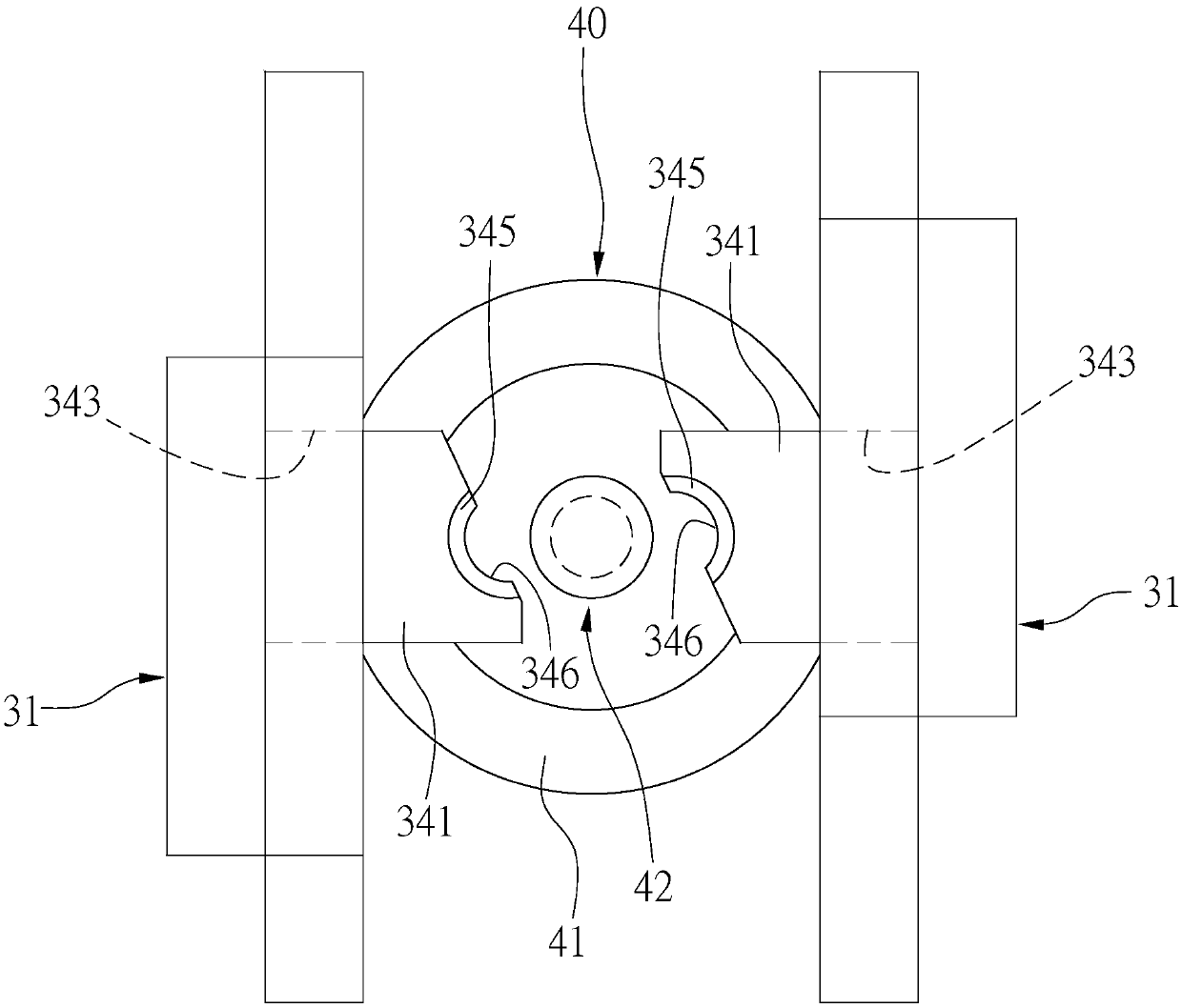
[0022] see Figure 1 to Figure 6 , those shown in the figure are preferred embodiments selected by the present invention, which are for illustration purposes only, and are not limited by the embodiments in the patent application.

[0023] Such as Figure 1 to Figure 3 As shown, the present invention provides a tool clamping structure, which is mainly composed of a set of seat body 11, a driving mechanism 21 and two clamping arms 31 arranged on the tool changing mechanism, wherein:

[0024] The driving mechanism 21 is disposed on the base body 11 , and the driving mechanism 21 is composed of a driving unit 22 and at least one telescopic rod 23 .

[0025] Two clamping arms 31, which are combined on the telescopic rod 23, and can drive the telescopic rod 23 to drive the clamping arm 31 through the drive unit 22, so that the two clamping arms 31 can move toward each other and are in a clamping position A The two clamping arms 31 have a first clamping portion 33 and a second clam...


PUM


Abstract

A cutter clamping structure of a tool changing mechanism comprises a seat body, a driving mechanism and two clamping arms. The driving mechanism consists of a driving unit and a telescopic rod and isarranged on the seat body. The clamping arms arranged on the telescopic rod can be driven by the driving unit to move. The two clamping arms have a first clamping portion and a second clamping portion. The second clamping portion is composed of a clamping block and an elastic piece, the clamping block can move towards a direction away from the first clamping portion through elastic abutting of theelastic piece, and the two clamping arms can make a cutter be clamped on the clamping arms stably through clamping of the first clamping portion and the clamping block and elastic abutting of the elastic piece towards the clamping block.

Description

technical field [0001] The invention relates to a tool clamping device of a tool changing mechanism, in particular to an improved structure for tool clamping. Background technique [0002] The tool clamping device on the existing tool changing mechanism mainly fixes the tool clamping through a clamping arm composed of two clamping arms, and pivots the clamping arm to a designated position through a driving device for tool exchange. However, the above-mentioned tool clamping device mainly fixes the tool by having a clamping section corresponding to the shape of the tool through its two clamping arms. The holding device only fixes the tool clamping through the oblique cone-shaped knife clamping section. As a result, when the tool clamping device is pivoted, centrifugal force is generated due to the swing of the pivot, and the tool is likely to be separated from the clamping arm along the knife clamping section. , so that the tool exchange cannot be carried out smoothly. [0...

Claims


Application Information

Patent Timeline
Patent Type & Authority Applications(China)
IPC IPC(8): B23Q3/155
CPCB23Q3/1554
Inventor 刘兴荣
Owner NEW GIFU ENTERPRISE
Why Eureka
Try Eureka