

Moveable blade for lever type plate shearing machine
The technology of a shearing machine and a moving blade is applied to the cutting tools, shearing devices, metal processing equipment and other directions of the shearing machine device, which can solve the problems of poor safety, easy to bite the moving blade, and the material to be cut hurts people. , to achieve the effect of stable feeding, reliable grasping and good safety
Inactive Publication Date: 2013-04-03
LIYANG FUCHANG MACHINERY
View PDF1 Cites 1 Cited by
- Summary
- Abstract
- Description
- Claims
- Application Information
AI Technical Summary
Problems solved by technology
The defect of the moving blade of this structure is: the existing lever type shearing machine is manually fed, and in the process of pushing the material to be sheared, the moving blade is easy to bite the material, so that one end of the material to be sheared is lifted. Causes the phenomenon of material to be cut to hurt people, and the safety is poor
Method used
View moreImage
Smart ImageViewing Examples

Examples
Embodiment
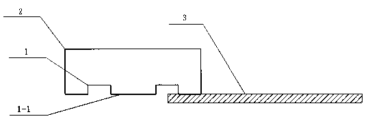
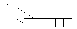
[0014] like figure 1 and figure 2 As shown, a movable blade for a lever type shearing machine is composed of a blade body 1 with a knife edge 1-1 at one end, and a groove 2 is opened on the blade body 1, and two grooves 2 are provided.
[0015] When the present invention is used, as figure 1 As shown, the material 3 to be cut is pushed from one side of the blade body 1 into between the movable blade of the lever shearing machine and the matching fixed blade, and after being cut by the movable blade and the fixed blade, the cut is completed. The material is pulled out from the other side of the blade body 1.
Login to View More PUM
 Abstract
The invention relates to a shearing machine, especially relates to a moveable blade for a lever type plate shearing machine and belongs to the technical field of manufacturing and processing of mechanical equipment. The moveable blade is composed of a blade main body (1) with a blade edge (1-1) at one end, wherein a slot (2) is formed on the blade main body (1). According to the invention, the slot is formed on the blade main body, the purpose of firmly grasping a propelled to-be-sheared material is achieved through the slot and the to-be-sheared material is free from material-biting phenomenon, so that the feeding is stable, the grasping is firm, the shearing effect is good, the phenomenon of hurting people by the to-be-sheared material is avoided and the safety is excellent during the process of propelling the to-be-sheared material by the moveable blade.
Description
technical field [0001] The invention relates to a shearing device, in particular to a movable blade for a lever type shearing machine. The invention belongs to the technical field of mechanical equipment manufacturing and processing. Background technique [0002] The shearing machine adopts a reasonable blade gap, uses the moving moving blade and the fixed fixed blade to apply shearing force to the plates of various thicknesses, so that the plates are broken and separated according to the requirements. [0003] Chinese Patent Publication No. CN201755688U discloses a cylinder-driven shearing machine, which includes a workbench, a bed, an upper knife seat and a pull bar. Sliding fit, the upper end of the tie rod is fixedly connected with the upper knife seat; the cylinder-driven shearing machine also includes a cylinder, a lever and an air compressor; the cylinder block is fixed on the bottom of the workbench; the lever fulcrum is hinged with the bed, and the lever power poi...
Claims
Login to View More Application Information
Patent Timeline
 Patent Type & AuthorityApplications(China)
IPC IPC(8): B23D35/00
Inventor魏峰
OwnerLIYANG FUCHANG MACHINERY