
Anti-slope-slipping structure with warning function

An anti-slip and functional technology, applied in the directions of roads, road signs, traffic signals, etc., can solve the problems of lack of initiative and insignificant effect, so as to improve the warning effect, reduce the probability of collision accidents, and reduce the occurrence of traffic accidents. The effect of the probability of

Inactive Publication Date: 2020-03-27
张润琛
View PDF10 Cites 9 Cited by
  • Summary
  • Abstract
  • Description
  • Claims
  • Application Information

AI Technical Summary

Problems solved by technology

[0003] Today's shopping malls or residential areas are equipped with underground parking garages. Due to the popularity of automatic gates, some vehicles will wait for identification and release on the slope during the peak period when the underground garage enters and exits. The existing slopes increase the friction coefficient of the ground. Improve the effect of anti-slip slope, but its effect is not obvious. In addition, it is generally not active to observe through the convex mirror on the road at the exit of the garage.

Method used


Image

  • Anti-slope-slipping structure with warning function
  • Anti-slope-slipping structure with warning function
  • Anti-slope-slipping structure with warning function

Examples


Embodiment 1

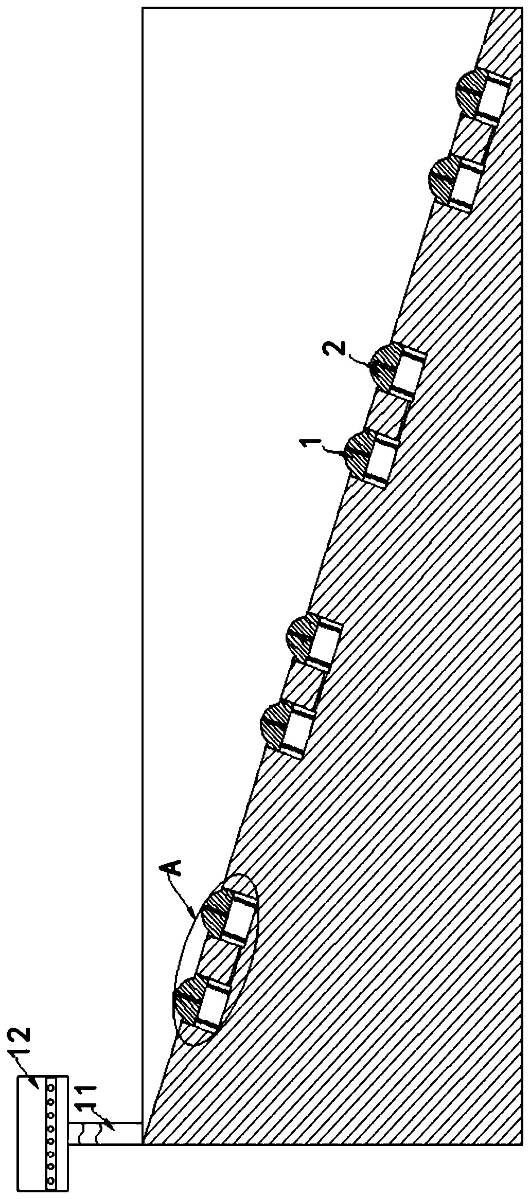
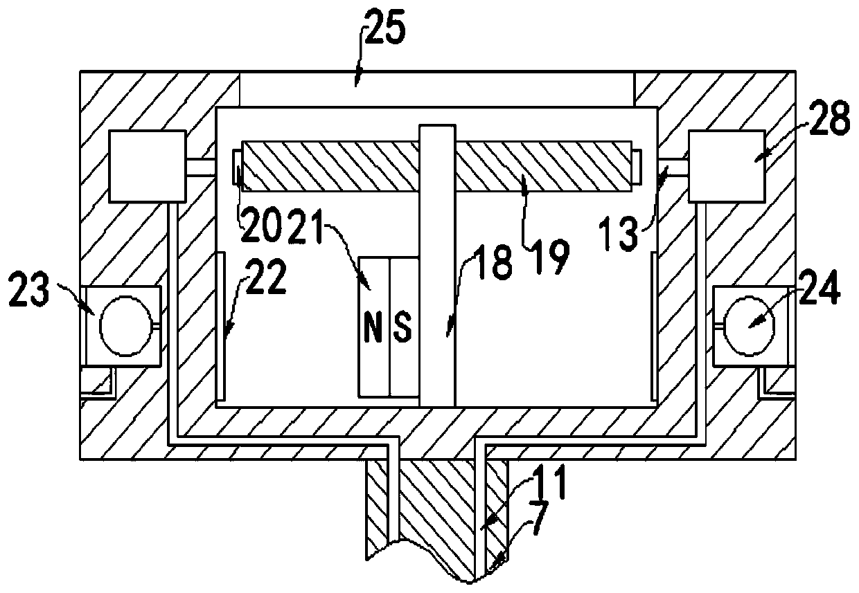
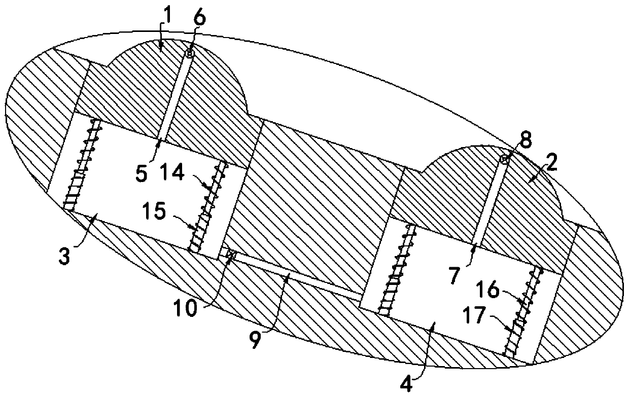
[0022] refer to Figure 1-4 , an anti-slope structure with a warning function, including a first deceleration belt 1, a second deceleration belt 2 and a slope for installing the first deceleration belt 1 and the second deceleration belt 2, and there are multiple first deceleration belts on the slope Groove 3 and a plurality of second grooves 4, the first deceleration belt 1 is slidingly sealed in the first groove 3, and the bottom of the first groove 3 is directly fixedly connected with the first deceleration belt 1 with a plurality of first buffers Assemblies, the side wall of the first deceleration belt 1 is provided with an air inlet 5 communicating with the first groove 3, and a first one-way pressure valve 6 is installed in the air inlet 5, wherein, after the first one-way pressure The air of the valve 6 can only flow into the first groove 3 from the outside, and the second deceleration belt 2 is slidingly sealed in the second groove 4. It should be noted that the first d...

Embodiment 2

[0029] The difference between this embodiment and Embodiment 1 is that a sealing plate 26 is fixedly installed in the opening 25, and an explosion opening 27 is arranged on the sealing plate 26. technology, so I won’t go into details here.

[0030] In this embodiment, when the air entering the warning box 12 is discharged to the outside through the explosion port 27, it can produce a piercing sound, which can further improve the safety warning function of the device at the exit of the garage by cooperating with the flashing lights.


PUM


Abstract

The invention discloses a slope sliding prevention structure with a warning function. The deceleration strip comprises a first deceleration strip body, a second deceleration strip body and a slope used for installing the first deceleration strip body and the second deceleration strip body. A plurality of first grooves and a plurality of second grooves are formed in the slope; the first deceleration strip is arranged in the first groove in a sliding and sealing manner; the bottom of the first groove and the first deceleration strip are directly and fixedly connected with a plurality of first buffer assemblies; an air inlet hole communicated with the first groove is formed in the side wall of the first deceleration strip; a first one-way pressure valve is installed in the air inlet hole, thesecond deceleration strip is arranged in the second groove in a sliding and sealing mode, a plurality of second buffer assemblies are fixedly connected between the bottom of the second groove and thesecond deceleration strip, an air guide pipe communicated with the second groove is arranged on the second deceleration strip in a penetrating mode, and a second one-way pressure valve is installed in the air guide pipe. The vehicle anti-slip device can effectively improve the anti-slip effect of an vehicle when the vehicle goes uphill, and also has a certain warning effect.

Description

technical field [0001] The invention relates to the technical field of slope prevention, in particular to a slope prevention structure with a warning function. Background technique [0002] Speed ​​bumps, also called speed bumps, are traffic facilities installed on highways to slow down passing vehicles. The shape is generally strip-shaped, and also dot-shaped; the material is mainly rubber, and there are also metal; generally yellow and black are used to attract visual attention, and the road surface is slightly arched to achieve the purpose of vehicle deceleration. It is generally installed on highway crossings, industrial and mining enterprises, schools, residential quarters, etc., where vehicles need to slow down and where traffic accidents are likely to occur. It is a new type of special traffic safety setting for reducing the speed of motor vehicles and non-motor vehicles. [0003] Today's shopping malls or residential areas are equipped with underground parking garag...

Claims


Application Information

Patent Timeline
Patent Type & Authority Applications(China)
IPC IPC(8): E01F9/529E01F13/04
CPCE01F13/046E01F9/529
Inventor 张润琛
Owner 张润琛
Learn More