Ceiling putty painting device

A ceiling and putty technology, applied in the direction of construction and building structure, can solve the problems of uneven coating, low work efficiency of workers, and a lot of labor, so as to avoid the effect of continuous discharge.

Active Publication Date: 2020-03-27
广东粤冠建材有限公司
View PDF10 Cites 2 Cited by
  • Summary
  • Abstract
  • Description
  • Claims
  • Application Information

AI Technical Summary

Problems solved by technology

[0002] During interior decoration, applying putty to walls and ceilings is a relatively complicated matter that requires a lot of manual work. When working, workers need the assistance of stairs, and then use tools to apply putty on the ceiling. The process is very tedious and time-consuming , and higher requirements for workers
[0003] At present, when applying putty to the ceiling, the workers need to use the stairs, and use tools to apply the putty on the ceiling on the stairs, which will reduce the work efficiency of the workers for a long time, resulting in uneven application

Method used


Image

  • Ceiling putty painting device
  • Ceiling putty painting device
  • Ceiling putty painting device

Examples


Embodiment 1

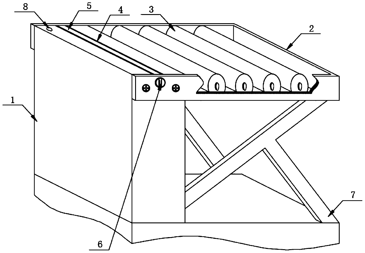
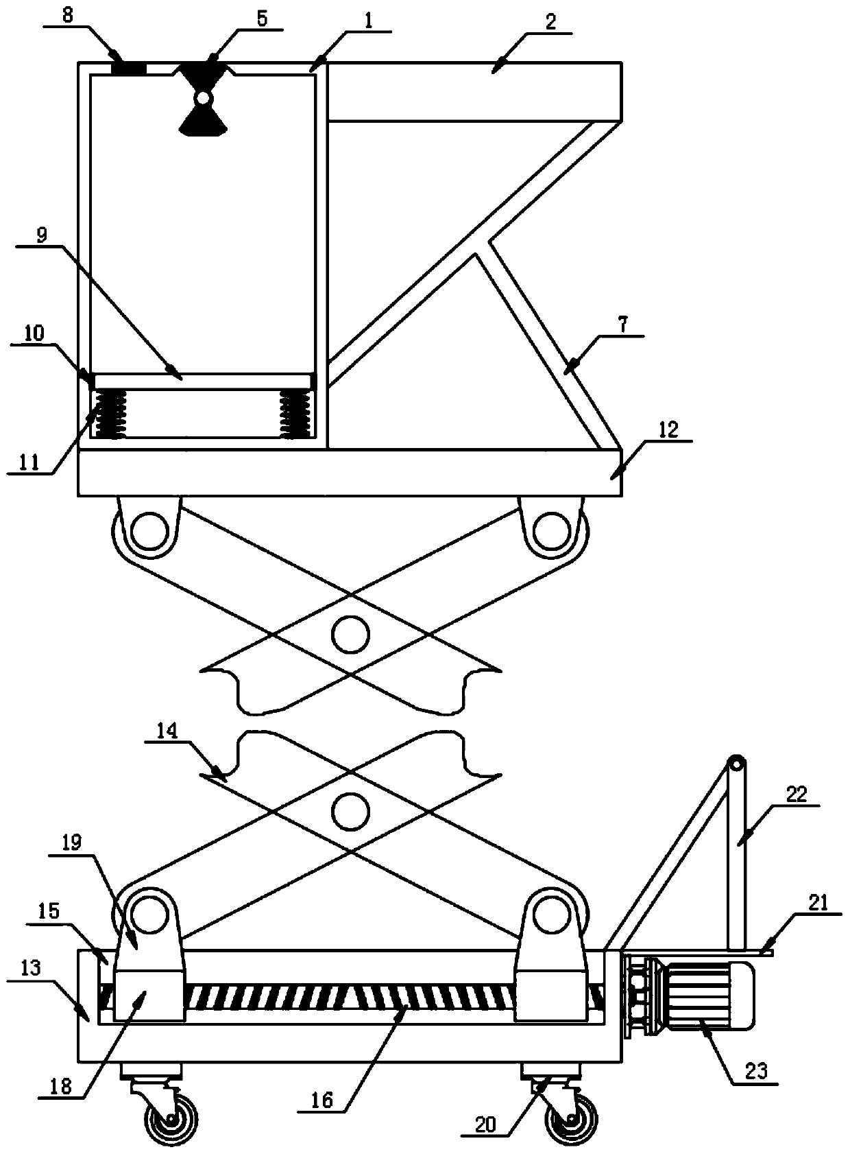
[0028] Such as Figure 1-2 and Figure 5 As shown, the present invention provides a ceiling smearing putty device, including a smearing device, a base plate 13, a traveling wheel 20 and a lifting device, the bottom four corners of the base plate 13 are equipped with a traveling wheel 20, and the top of the base plate 13 is provided with a lifting device , A smearing device is installed on the lifting device.

[0029] The smearing device includes a material box 1, a fixed frame 2, a cylinder 3, a sealing plate 5, a knob 6, a support 7, a movable plate 9, a sealing ring 10 and a spring 11, and the top left side of the lifting device is provided with a material box 1, and the material There is a feeding port 8 on the left side of the top of the box 1. There is a sliding movable plate 9 in the material box 1 that can push the putty to move. The side wall of the movable plate 9 is equipped with a sealing ring 10, which can effectively prevent the movable plate in the material box ...

Embodiment 2

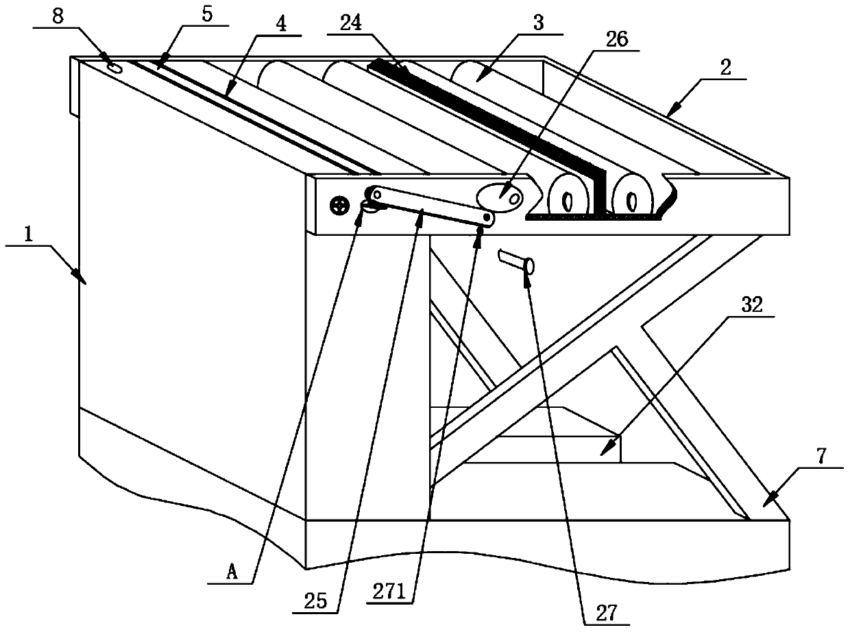
[0033] Such as Figure 3-4 and Figure 6-8 As shown, the difference from Embodiment 1 is that one side of the fixed frame 2 is provided with a linkage mechanism. , torsion spring 30, guide rod 33, seesaw 34, ejector rod 36, sleeve 37 and stay cord 38, described knob 6 front side is fixedly connected with turning plate 25, and the left side below turning plate 25 is provided with baffle plate 28, All have guide groove 31 in the middle of baffle plate 28 tops and baffle plate 28 bottom left sides, feed box 1 front side upper part is fixedly connected with fixed rod 29, is provided with torsion spring 30 on the fixed rod 29, and the two ends of torsion spring 30 and up and down The guide grooves 31 on both sides are fixedly connected, and the front end of the leftmost cylinder 3 is fixedly connected with an elliptical plate 26. The elliptical plate 26 is in contact with the flipping plate 25, and the middle of the right part of the flipping plate 25 and the left side of the fron...


PUM


Abstract

The invention discloses a ceiling putty painting device, and particularly relates to the field of putty painting equipment. The ceiling putty painting device includes a painting device and a lifting device, wherein the painting device includes a material box, a fixed frame is fixedly installed on one side of the material box by bolts, the fixed frame is movably provided with a plurality of rollers, a discharge hole is formed in the middle of the material box top, the material box is internally provided with a discharge device, the discharge device includes springs, and the springs are fixedlyinstalled at the four corners of the bottom of an inner cavity of the material box. According to the ceiling putty painting device, a motor is used for driving a threaded rod to rotate so that slidingblocks at two ends of the threaded rod can move in the opposite direction, a telescopic frame is extended, then the painting device provided with the putty is lifted to be in contact with the top ofthe ceiling, then a rotary knob is opened, so that the putty in the material box is extruded out under the restoring force of the springs, and a staff only needs to push a push frame below, so that walking wheels at the bottom of a base plate rolls on the ground to realize the uniform painting of the putty.

Description

technical field [0001] The invention relates to the field of putty application equipment, more specifically, the invention relates to a ceiling application putty device. Background technique [0002] During interior decoration, applying putty to walls and ceilings is a relatively complicated matter that requires a lot of manual work. When working, workers need the assistance of stairs, and then use tools to apply putty on the ceiling. The process is very tedious and time-consuming , and have higher requirements for workers. [0003] At present, when applying putty to the ceiling, workers need to use the stairs, and use tools to apply the putty on the ceiling on the stairs, which will make the work efficiency of the workers low for a long time, resulting in uneven application. Contents of the invention [0004] In order to overcome the above-mentioned defects of the prior art, an embodiment of the present invention provides a device for applying putty on the ceiling. By us...

Claims


Application Information

Patent Timeline
Patent Type & Authority Applications(China)
IPC IPC(8): E04F21/08
CPCE04F21/08
Inventor 罗登云
Owner 广东粤冠建材有限公司
Why Eureka
Try Eureka