Wafer cleaning liquid recovery equipment

A technology for recycling equipment and cleaning fluids, which is applied in electrical components, semiconductor/solid-state device manufacturing, circuits, etc., and can solve problems such as manual determination, incomplete sorting and recycling, and trouble.

CN110931394AInactive Publication Date: 2020-03-27王挺
1 Cites 2 Cited by

Patent Information

Authority / Receiving Office
CN · China
Patent Type
Applications(China)
Current Assignee / Owner
Publication Date
2020-03-27
Estimated Expiration
Not applicable · inactive patent

Smart Images

  • Figure 1
    Figure 1
  • Figure 2
    Figure 2
  • Figure 3
    Figure 3
Patent Text Reader

Abstract

The invention discloses wafer cleaning fluid recovery equipment. The wafer cleaning fluid recovery equipment structurally comprises a movable recovery device, a shielding device, a fluid director, a turntable, a rotating shaft, a motor and a pushing device, wherein the bottom of the turntable is connected with the rotating shaft; the bottom of the rotating shaft is connected with the motor arranged in the fluid director; the shielding device is arranged on the left side of the fluid director; the movable recovery device is mounted below the fluid director; a movable recovery tank is movably connected with the pushing device; the fluid director comprises side plates, an inclined plate, a coaming and a bottom plate; the bottom of the coaming is connected with the bottom plate; two ends of the coaming are respectively connected with the side plates; the inclined plate is connected with the bottom plate and the coaming; and the movable recovery device includes a sliding rail, a recycling groove, an output pipe, a partition plate and a support plate. The wafer cleaning fluid recovery equipment has the beneficial effects that through the design, cleaning liquid can directly flow into thecorresponding recovery tank, and the phenomenon of splashing or water leakage cannot occur, and the type of the cleaning liquid can be judged through the PH value, and the position of the recovery tank is automatically adjusted, and the wafer cleaning fluid recovery equipment is more intelligent.
Need to check novelty before this filing date? Find Prior Art

Description

technical field

[0001] The invention relates to the field of wafer processing, in particular to a wafer cleaning liquid recycling device. Background technique

[0002] Wafer refers to the silicon wafer used in the production of silicon semiconductor integrated circuits. Because of its circular shape, it is called a wafer; it can be processed into various circuit element structures on the silicon wafer, and becomes an integrated circuit with specific electrical functions. circuit products.

[0003] The existing patent No. 201711167935.9 wafer cleaning liquid recovery device includes a recovery unit, a lifting unit and a discharge unit, and the recovery unit includes a plurality of annular recovery tanks arranged continuously in the vertical direction; The unit is used to control the recovery unit to move in the vertical direction, so that the plurality of recovery tanks on the recovery unit are used to recover different wafer cleaning liquids respectively; the discharge unit...

Examples

Embodiment Construction

[0025] The following will clearly and completely describe the technical solutions in the embodiments of the present invention with reference to the accompanying drawings in the embodiments of the present invention. Obviously, the described embodiments are only some, not all, embodiments of the present invention. Based on the embodiments of the present invention, all other embodiments obtained by persons of ordinary skill in the art without making creative efforts belong to the protection scope of the present invention.

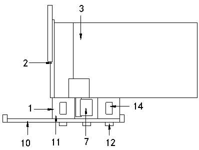
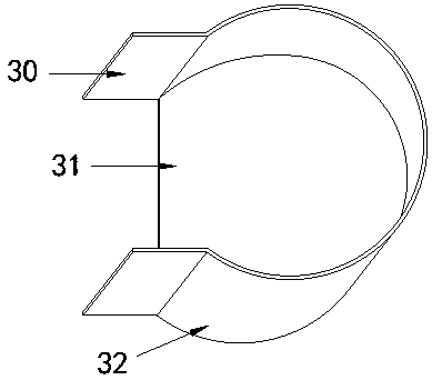
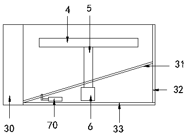
[0026] see Figure 1-6 , the present invention provides a technical solution for wafer cleaning liquid recovery equipment: its structure includes a mobile recovery device 1, a shutter 2, a deflector 3, a turntable 4, a rotating shaft 5, a motor 6, and a pushing device 7. The bottom of the turntable 4 It is connected with the rotating shaft 5, the bottom of the rotating shaft 5 is connected with the motor 6 arranged in the deflector 3, the left side of the defl...