
A self-propelled cable laying device

A laying device and cable technology, applied in the direction of cable installation, cable laying equipment, ground cable installation, etc., can solve problems such as cable twisting and cable damage, and achieve the effect of ensuring reliability

Active Publication Date: 2020-11-10
海南电力产业发展有限责任公司
View PDF8 Cites 0 Cited by
  • Summary
  • Abstract
  • Description
  • Claims
  • Application Information

AI Technical Summary

Problems solved by technology

[0002] In the process of laying long-distance cables, because the cables need to be rolled together, it is easy to cause the cables to be twisted in the retracted state. When laying work, it is easy to cause the twisted cables to be laid on the cable without reset. In the ditch, and when laying, due to the unevenness of the laying ground, the cable will be shaken and further twisted during laying, which will cause the cable to be easily damaged by torsion after long-term use

Method used


Image

  • A self-propelled cable laying device
  • A self-propelled cable laying device
  • A self-propelled cable laying device

Examples


Embodiment Construction

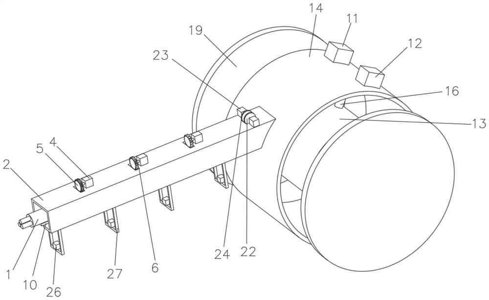
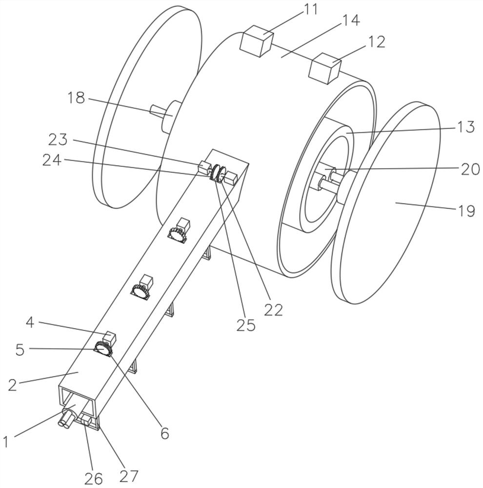
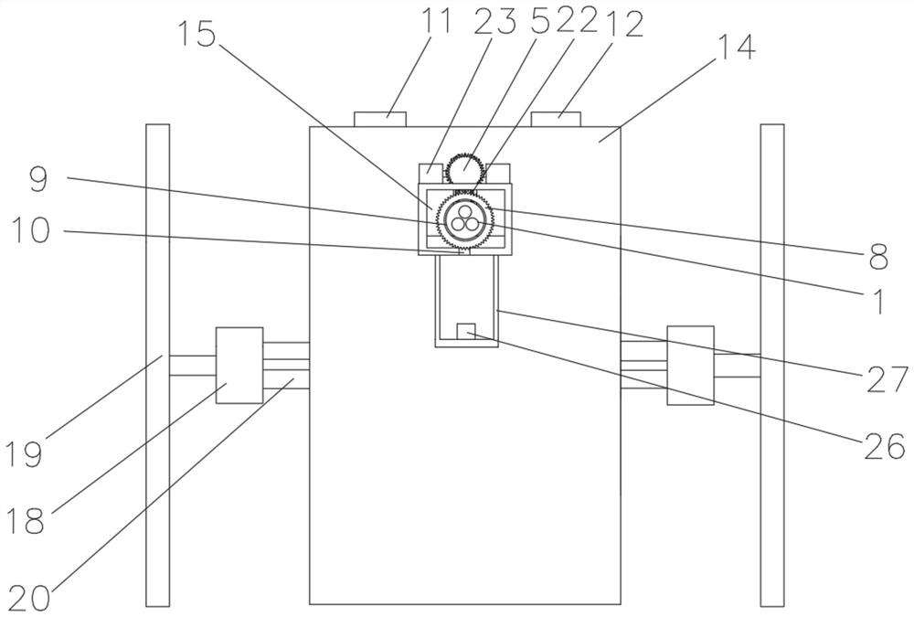
[0022] In order to better understand the technical content of the present invention, specific embodiments are provided below, and the present invention is further described in conjunction with the accompanying drawings.

[0023] see Figure 1 to Figure 7 , a self-propelled cable laying device of the present invention, comprising a retracting mechanism for retracting a cable 1, a release tube 2 for releasing a cable 1, and a cable 1 with a coaxial mark 3 on the surface, the cable 1 Wrapped in the retracting mechanism, the release tube 2 communicates with the retracting mechanism, the retracting mechanism is provided with a drive mechanism, and the release tube 2 is provided with a push mechanism for driving the cable 1 to move , the outer wall of the release pipe 2 is provided with a number of first motors 4, and the output end of the first motor 4 is provided with a first gear 5, and the number of teeth of the different first gears 5 moves along the release pipe 2 from the top...


PUM


Abstract

The invention discloses a cable self-walking laying device. The device comprises a winding mechanism used for winding a cable, a release pipe used for releasing the cable and a cable with a coaxial mark on the surface. A cable is wound in the winding mechanism; the release pipe is communicated with the winding mechanism; a driving mechanism is arranged on the winding mechanism; a pushing mechanismis arranged on the release pipe; a plurality of first motors are arranged on the outer wall of the release pipe; a first gear is arranged at the output end of the first motor; the tooth numbers of the different first gears are gradually increased from top to bottom along the release pipe; a through groove is formed in the top of the release pipe; a plurality of closed-loop-shaped grooves are formed in the inner wall of the release pipe; the through groove is communicated with the groove; a second gear is arranged in the groove; and the tooth numbers of the different second gears are graduallyincreased from top to bottom along the release pipe; the first gear is meshed with the second gear, a through hole is formed in the middle of the second gear, a cable penetrates through the through hole, a strip-shaped groove is formed in the bottom of the release pipe, the torsion degree of the cable can be reduced, and resetting is conducted according to the torsion degree of the cable.

Description

technical field [0001] The invention belongs to cable laying equipment, in particular to a cable self-propelled laying device. Background technique [0002] In the process of laying long-distance cables, because the cables need to be rolled together, it is easy to cause the cables to be twisted in the retracted state. When laying work, it is easy to cause the twisted cables to be laid on the cable without reset. In the ditch, and when laying, due to the unevenness of the laying ground, the cable will be shaken and further twisted during laying, which will cause the cable to be easily damaged by torsion after long-term use. Contents of the invention [0003] The problem to be solved by the present invention is a cable self-propelled laying device that can reduce the twisting degree of the cable during the laying process and perform effective reset according to the twisting degree of the cable. [0004] A cable self-propelled laying device of the present invention comprises...

Claims


Application Information

Patent Timeline
Patent Type & Authority Patents(China)
IPC IPC(8): H02G1/08H02G9/02
CPCH02G1/08H02G9/02
Inventor 吴天杰黄雄林少佳黄日瑞岑琼霞陈锐忠程范贤王崇鲁
Owner 海南电力产业发展有限责任公司
Learn More