Beam indication method and device

An indication and beam technology, applied in network planning, transmission system, wireless communication, etc., can solve the problem of high scheduling overhead and achieve the effect of saving scheduling overhead

Active Publication Date: 2020-03-27
CHENGDU HUAWEI TECH
View PDF15 Cites 5 Cited by
  • Summary
  • Abstract
  • Description
  • Claims
  • Application Information

AI Technical Summary

Problems solved by technology

However, the transmission of uplink signals and the reception of downlink signals are independently scheduled, and the scheduling overhead is relatively large.

Method used


Image

  • Beam indication method and device
  • Beam indication method and device
  • Beam indication method and device

Examples


Embodiment Construction

[0063] The technical solution in this application will be described below with reference to the accompanying drawings.

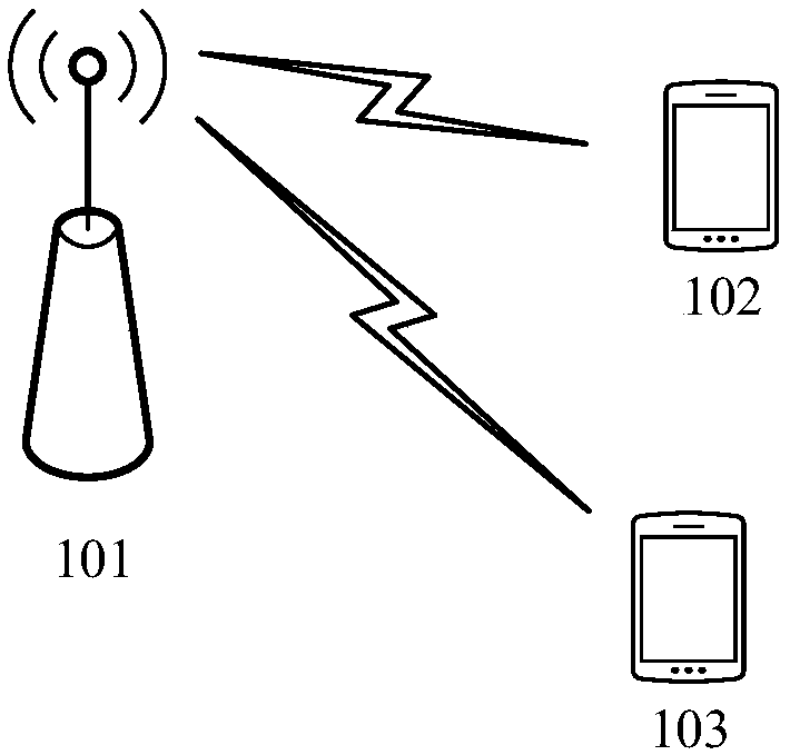
[0064] see figure 1 , figure 1 is a schematic diagram of the wireless communication system 100 applicable to the embodiment of the present application. Such as figure 1 As shown, the wireless communication system 100 may include at least one network device 101, and the network device 101 communicates with one or more terminal devices (for example, figure 1 The terminal device 102 and the terminal device 103 shown in ) perform wireless communication.

[0065]The wireless communication system 100 involved in this application includes but not limited to global system of mobile communication (GSM) system, code division multiple access (code division multiple access, CDMA) system, wideband code division multiple access (wideband code division) multiple access (WCDMA) system, general packet radio service (general packet radio service, GPRS), long term evolutio...


PUM


Abstract

Provided is a beam indication method, which can save the scheduling overhead of downlink signal reception and uplink signal transmission. The method comprises: receiving first information from networkequipment, wherein the first information is used for determining a first receiving beam of a downlink signal and a first sending beam of an uplink signal; and determining a first receiving beam of the downlink signal and a first sending beam of the uplink signal according to the first information.

Description

technical field [0001] The present application relates to the technical field of wireless communication, and in particular to a method and device for indicating a beam. Background technique [0002] In a long term evolution (long term evolution, LTE) communication system, terminal equipment receives downlink signals and transmits uplink signals based on base station scheduling. Usually, the scheduling of the downlink signal and the scheduling of the uplink signal are independently scheduled based on respective physical downlink control channels (physical downlink control channel, PDCCH). That is to say, the network device schedules the reception of downlink signals through one PDCCH, and then schedules the transmission of uplink signals through another PDCCH. [0003] However, in some scenarios that require centralized control, the reception of downlink signals and the transmission of uplink signals generally occur in pairs. For example, the controller sends an instruction...

Claims


Application Information

Patent Timeline
Patent Type & Authority Applications(China)
IPC IPC(8): H04W72/04H04L5/00
CPCH04W72/046H04L5/0048H04L5/0053H04W72/23H04B7/0695H04B7/088H04B7/0628H04B7/0621H04B7/086H04L5/0025H04L5/0094H04W16/28H04W72/53
Inventor 邵华余子明黄煌
Owner CHENGDU HUAWEI TECH
Why Eureka
Try Eureka