
Eureka
For R&D, Eureka makes reading and utilizing patents & technical documents easy.
Eureka AIR
Designed for self-driven R&D workflows. Generate viable solutions, solve complex R&D challenges, empower your innovation with AI.

Eureka Materials
Designed for material experts only. Revolutionize your material R&D, from search, analyze, to developing new materials.

TechResearch
Generate reliable direction feasibility study reports for your R&D in just a few steps.

TechSeek
Discover and master advanced knowledge NOW. Basics, ideas, possibilities, all at once.

TechMind
As an expert in R&D Theories, TechMind can generates customized viable solutions instantly.

TechRisk
Analyze your overall solution with one click, know your potential R&D risks in advance.

TechMonitor
Get weekly tech updates, stay abreast of the latest tech innovations and key insights.
Method for casting metal strip with edge control
A metal, edge thickness technology used in the field of cast metal strips to solve problems affecting product quality, response delays, etc.
- Summary
- Abstract
- Description
- Claims
- Application Information
AI Technical Summary
Problems solved by technology
Method used
Image

Examples
Embodiment Construction
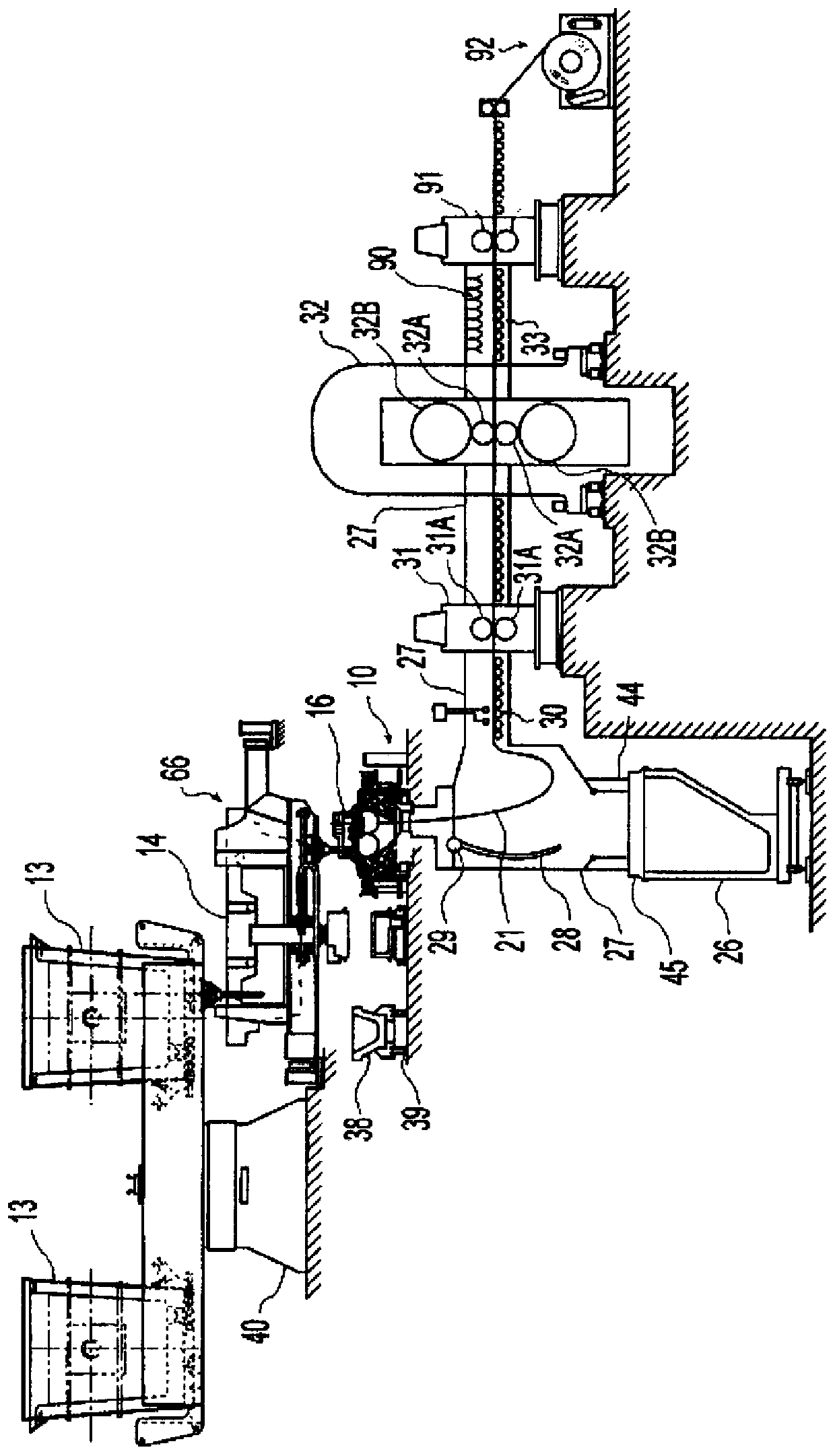
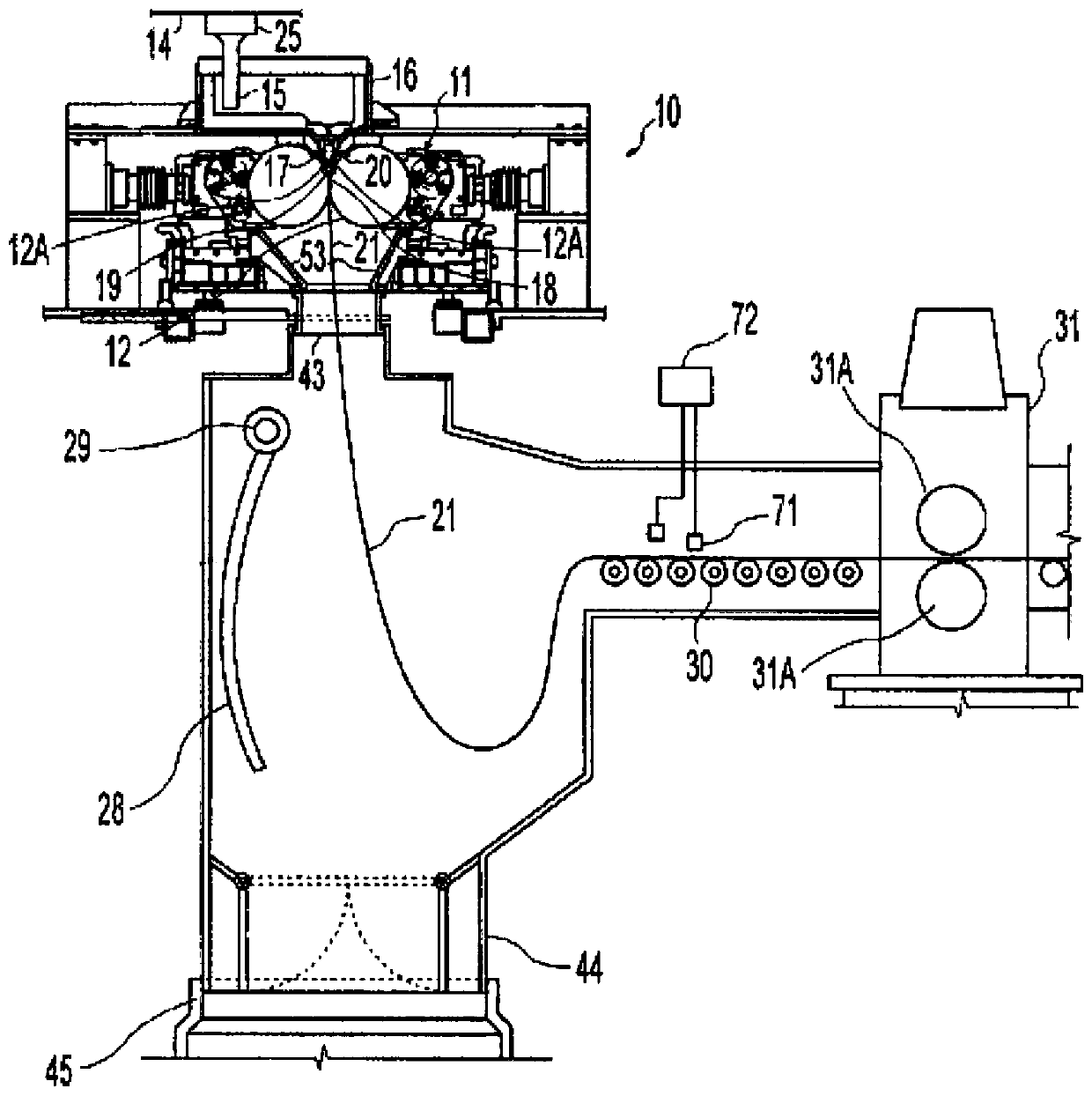
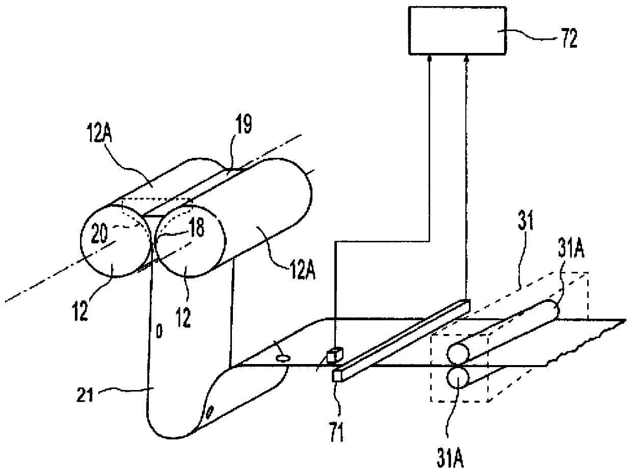
[0085] now refer to figure 1 , 2 and 2A, which show a twin roll caster comprising a main frame 10 that rises above the factory floor and supports a pair of modules mounted in roll cassettes 11 that can Counter-rotating casting rolls 12. Casting rolls 12 are mounted in roll cassettes 11 for ease of handling and movement, as described below. The roll cassette 11 facilitates the rapid movement of the casting rolls 12 ready for casting as a unit in the casting machine from the setup position to the working casting position and facilitates the rapid removal of the casting rolls 12 from the casting position when the casting rolls 12 need to be replaced . The roll cassette 11 need not be of any particular construction, so long as it functions to facilitate movement and positioning of the casting rolls 12 as described herein.
[0086] The casting apparatus for continuously casting thin steel strip comprises a pair of counter-rotatable casting rolls 12 having casting surfaces 12A a...
PUM
| Property | Measurement | Unit |
|---|---|---|
| thickness | aaaaa | aaaaa |
| thickness | aaaaa | aaaaa |
| thickness | aaaaa | aaaaa |
Abstract
Description
Claims
Application Information
 - R&D Engineer
- R&D Manager
- IP Professional
- Industry Leading Data Capabilities
- Powerful AI technology
- Patent DNA Extraction
Browse by: Latest US Patents, China's latest patents, Technical Efficacy Thesaurus, Application Domain, Technology Topic, Popular Technical Reports.
© 2024 PatSnap. All rights reserved.Legal|Privacy policy|Modern Slavery Act Transparency Statement|Sitemap|About US| Contact US: help@patsnap.com