Laser television cabinet and projection equipment
A TV cabinet and laser technology, applied in optics, cabinets, instruments, etc., can solve the problem of single function of TV cabinets, achieve the effect of flexible use, meet projection needs, and improve service life
- Summary
- Abstract
- Description
- Claims
- Application Information
AI Technical Summary
Problems solved by technology
Method used
Image
Examples
Embodiment 1
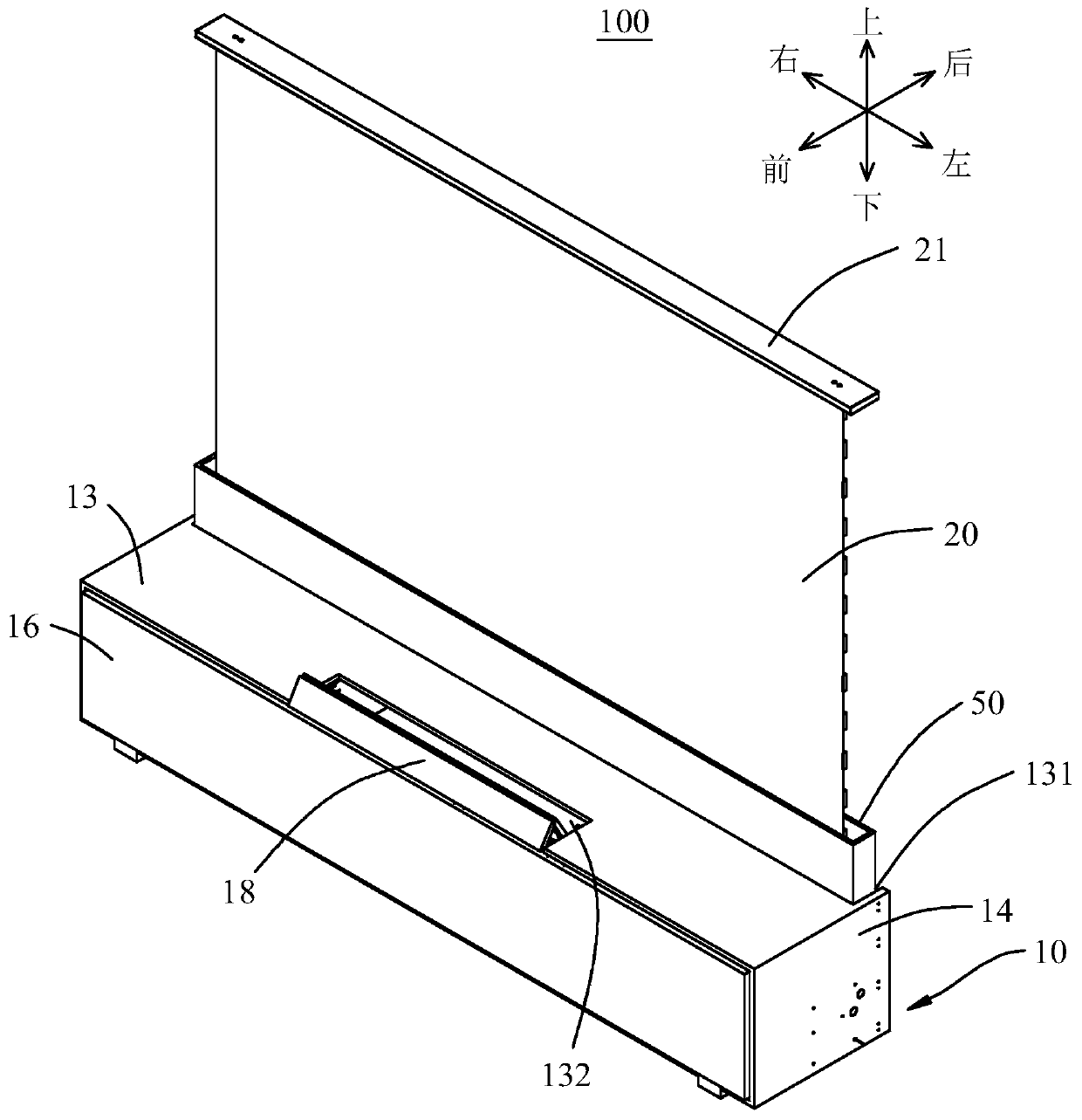
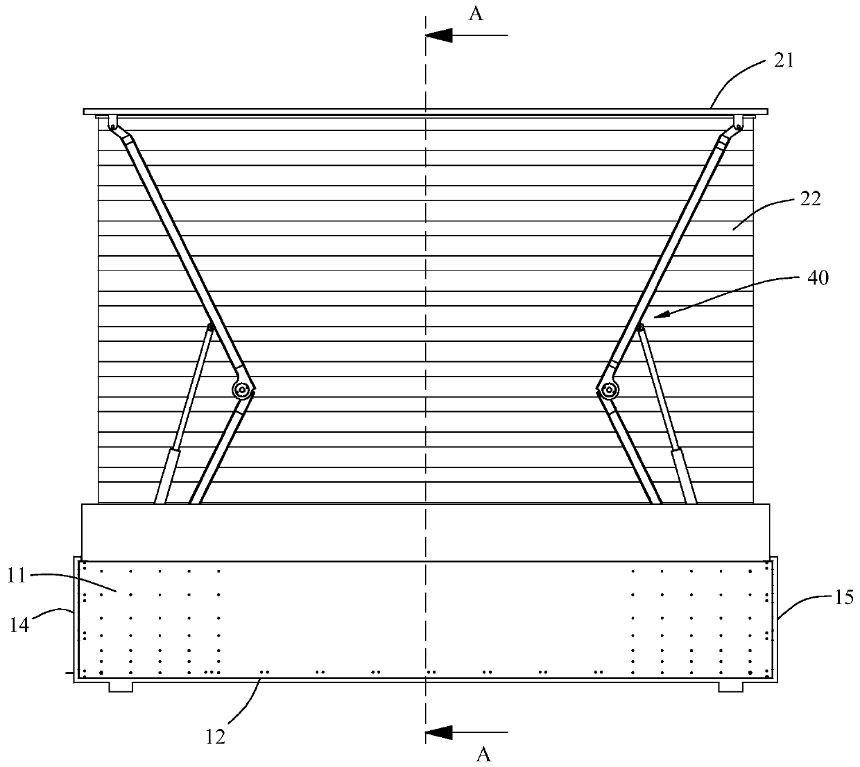
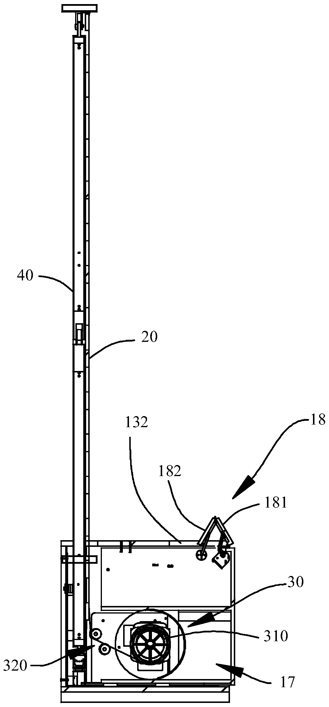
[0052] Such as figure 1 with figure 2 As shown, the laser TV cabinet 100 according to the embodiment of the present application is applied to ultra-short-focus projection, and includes: a cabinet body 10, a curtain 20, and a winding and unwinding mechanism 30 (such as image 3 Shown) and curtain lifting mechanism 40.
[0053] Specifically, the cabinet body 10 plays a role of positioning support, and the cabinet body 10 can be moved to a designated position according to needs, and the movement is flexible; the cabinet body 10 is provided with a place for placing a projector (not shown in the figure). Such as image 3 As shown, the rewinding and unwinding mechanism 30 is arranged in the cabinet 10, the rewinding and unwinding mechanism 30 includes a reel 310 and a rewinding and unwinding drive device (not shown in the figure), one end of the curtain 20 is wound on the reel 310, and the reel 310 The two ends are respectively installed on the cabinet body 10 and can rotate rel...
Embodiment 2
[0078] Such as Figure 10 As shown, according to the laser TV cabinet 200 of the embodiment of the present application, compared with the laser TV cabinet 100 of the first embodiment, the curtain lifting mechanism 60 of the laser TV cabinet 200 adopts a scissor lift structure, and other components are the same as those of the first embodiment. The components of the laser TV cabinet 100 are the same, and will not be described in detail in Embodiment 2.
[0079] Such as Figure 10 As shown, the curtain lifting mechanism 60 includes a guide rail 61, a second driving device 62, a screw nut mechanism 63, a first rotating rod 64 and a second rotating rod 65, and the guide rail 61 is fixed on the upper end (free end, namely the cover) of the curtain 20 plate 21), and extends along the width direction of the screen 20. The middle part of the first rotating rod 64 is hinged with the middle part of the second rotating rod 65 to form an X-shaped structure. Both the upper ends of the fi...
PUM
 Abstract
Description
Claims
Application Information
 - R&D
- Intellectual Property
- Life Sciences
- Materials
- Tech Scout
- Unparalleled Data Quality
- Higher Quality Content
- 60% Fewer Hallucinations
Browse by: Latest US Patents, China's latest patents, Technical Efficacy Thesaurus, Application Domain, Technology Topic, Popular Technical Reports.
© 2025 PatSnap. All rights reserved.Legal|Privacy policy|Modern Slavery Act Transparency Statement|Sitemap|About US| Contact US: help@patsnap.com


