Adjustable fire-fighting lance

An adjustable, fire-fighting technology

Inactive Publication Date: 2020-04-03
SHAANXI HUABANG TECH DEV CO LTD
View PDF2 Cites 0 Cited by
  • Summary
  • Abstract
  • Description
  • Claims
  • Application Information

AI Technical Summary

Problems solved by technology

[0003] Patent No. 201410715042.3 discloses a fire-fighting water gun with an injector that can increase the water pressure and flow rate through the booster tube on the injector, and has an injection chamber that can form an air cushion between the water flow and the injector layer, which can effectively reduce the friction between the water flow and the auxiliary spray tube, thereby greatly increasing the shooting range, but the thickness of the water column cannot be adjusted; the patent No. The water volume nozzle is set in a sleeve, and the size of the nozzle opening can be adjusted to adjust the water volume of the sprayed water. It is convenient to use, but it cannot be pressurized, and the water pressure and flow rate cannot be increased.

Method used


Image

  • Adjustable fire-fighting lance
  • Adjustable fire-fighting lance
  • Adjustable fire-fighting lance

Examples


Embodiment 1

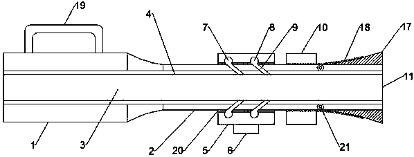
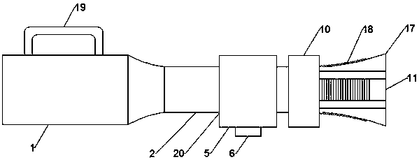
[0024] Such as Figure 1-3 As shown, the adjustable fire water gun according to the embodiment of the present invention includes a gun barrel 1 and a gun barrel 2 2, and the insides of the gun barrel 1 and the gun barrel 2 are respectively provided with cavities 3. The inside of the cavity 3 is provided with an inner tube 4, the gun barrel 2 is set with a pressurized sleeve 5, and the bottom end of the pressurized sleeve 5 is provided with an air inlet 6, and the inside of the pressurized sleeve 5 An annular air pipe one 7 and an annular air pipe two 8 communicating with the air inlet 6 are provided, and a number of pipes communicating with the annular air pipe one 7 and the annular air pipe two 8 are provided on the side wall of the gun barrel two 2 . Exhaust passage 9, described gun barrel two 2 is provided with the bolt 10 that is positioned at described pressurization sleeve 5 one side, and one end of described gun barrel two 2 is provided with shower nozzle 11, and descri...

Embodiment 2

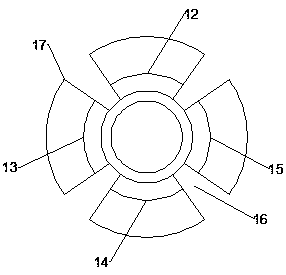
[0029] Such as Figure 1-3 As shown, the gun barrel one 1 is provided with a handle 19, the pressurized sleeve 5 and the gun barrel two 2 are provided with a sealing sleeve 20, the movable piece one 12, the movable piece two 13, The movable piece three 14 and the movable piece four 15 are connected with the gun barrel two 2 respectively through the movable shaft 21, the exhaust passage 9 is an inclined structure, and the inner tube 4 is soft The structure, the pressure plate 17 is an inclined structure, the sealing performance can be improved by setting the sealing sleeve 20, and the mobility can be improved by setting the movable shaft 21.

[0030] from Figure 1-3 It can be seen from the figure that the gun barrel one 1 is provided with a handle 19, the pressurized sleeve 5 and the gun barrel two 2 are provided with a sealing sleeve 20, the movable piece one 12, the movable piece two 13. The third movable piece 14, the fourth movable piece 15 and the second gun barrel 2 ar...


PUM


Abstract

The invention discloses an adjustable fire-fighting lance. The adjustable fire-fighting lance comprises a first gun barrel and a second gun barrel, cavities are formed in the first gun barrel and thesecond gun barrel correspondingly, inner pipes are arranged in the cavities, the second gun barrel is sleeved with a pressurizing sleeve, an air inlet is formed in the bottom end of the pressurizing sleeve, a first annular air pipe and a second annular air pipe are arranged in the pressurizing sleeve, a plurality of exhaust passages are formed in the side wall of the second gun barrel, a bolt is arranged on the second gun barrel, a spray head is arranged at one end of the second gun barrel, the spray head is composed of a movable piece I, a movable piece II, a movable piece III and a movable piece IV; one side of the movable piece I, the movable piece II, the movable piece III and the movable piece IV are each provided with a pressing plate, and the pressing plates are provided with threads matched with the bolts. The adjustable fire-fighting lance has the advantages that water pressure and flow speed can be effectively increased, the caliber of the nozzle can be adjusted, and thickness of a water column can be adjusted.

Description

technical field [0001] The invention relates to the technical field of fire-fighting water guns, in particular to an adjustable fire-fighting water gun. Background technique [0002] Among the fire extinguishing equipment, the fire spray gun is a necessity, which can spray high-pressure water flow to the fire source in different forms to extinguish the fire. Fire spray guns generally include interfaces, switches and nozzles for fire fighting. Existing fire nozzles can generally form different ranges, and in the process of fire fighting, the control of water volume is also an important factor. In different stages of fire treatment, the demand for sprayed water volume is also different. However, in the existing fire nozzles, it is difficult to adjust the spray water volume with the same spray gun, and the existing fire water guns cannot be pressurized when the water pressure is not enough, so it is inconvenient to use. [0003] Patent No. 201410715042.3 discloses a fire-figh...

Claims


Application Information

Patent Timeline
Patent Type & Authority Applications(China)
IPC IPC(8): A62C31/03A62C31/28
CPCA62C31/03A62C31/28
Inventor 姜宝海
Owner SHAANXI HUABANG TECH DEV CO LTD
Why Eureka
Try Eureka