
Resistance device

A resistance device and resistance technology, which is applied to sports accessories, muscle training equipment, gymnastics equipment and other directions, can solve the problems of increased resistance of pull ropes and threads, pressure lines, increased manufacturing cost and accuracy requirements of motor resistance devices, etc.

Pending Publication Date: 2020-04-03
XIAMEN LINGDONG LNTELLIGENT TECH CO LTD
View PDF5 Cites 2 Cited by
  • Summary
  • Abstract
  • Description
  • Claims
  • Application Information

AI Technical Summary

Problems solved by technology

[0003] However, the existing motor resistance device usually uses a thread structure to guide the rope to prevent the cross-winding of the pull cord, which increases the manufacturing cost and precision requirements of the motor resistance device, otherwise the wire may be pressed, and the gap between the pull cord and the thread friction increases resistance

Method used


Image

  • Resistance device
  • Resistance device
  • Resistance device

Examples


Embodiment Construction

[0054] In order to achieve the above-mentioned purpose and effect, the technical means and structure adopted by the present invention, the features and functions of the preferred embodiments of the present invention will be described in detail as follows in order to facilitate a complete understanding.

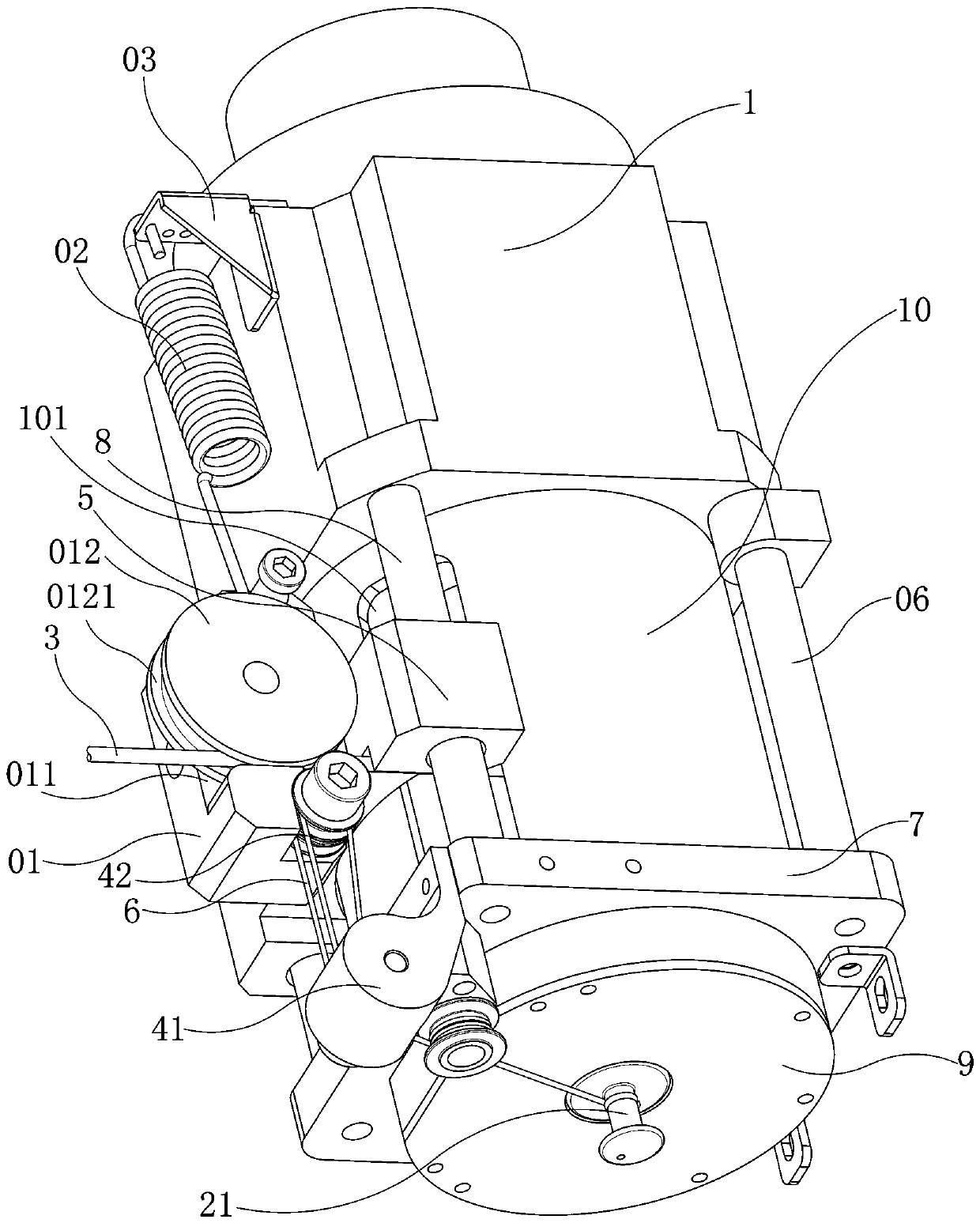
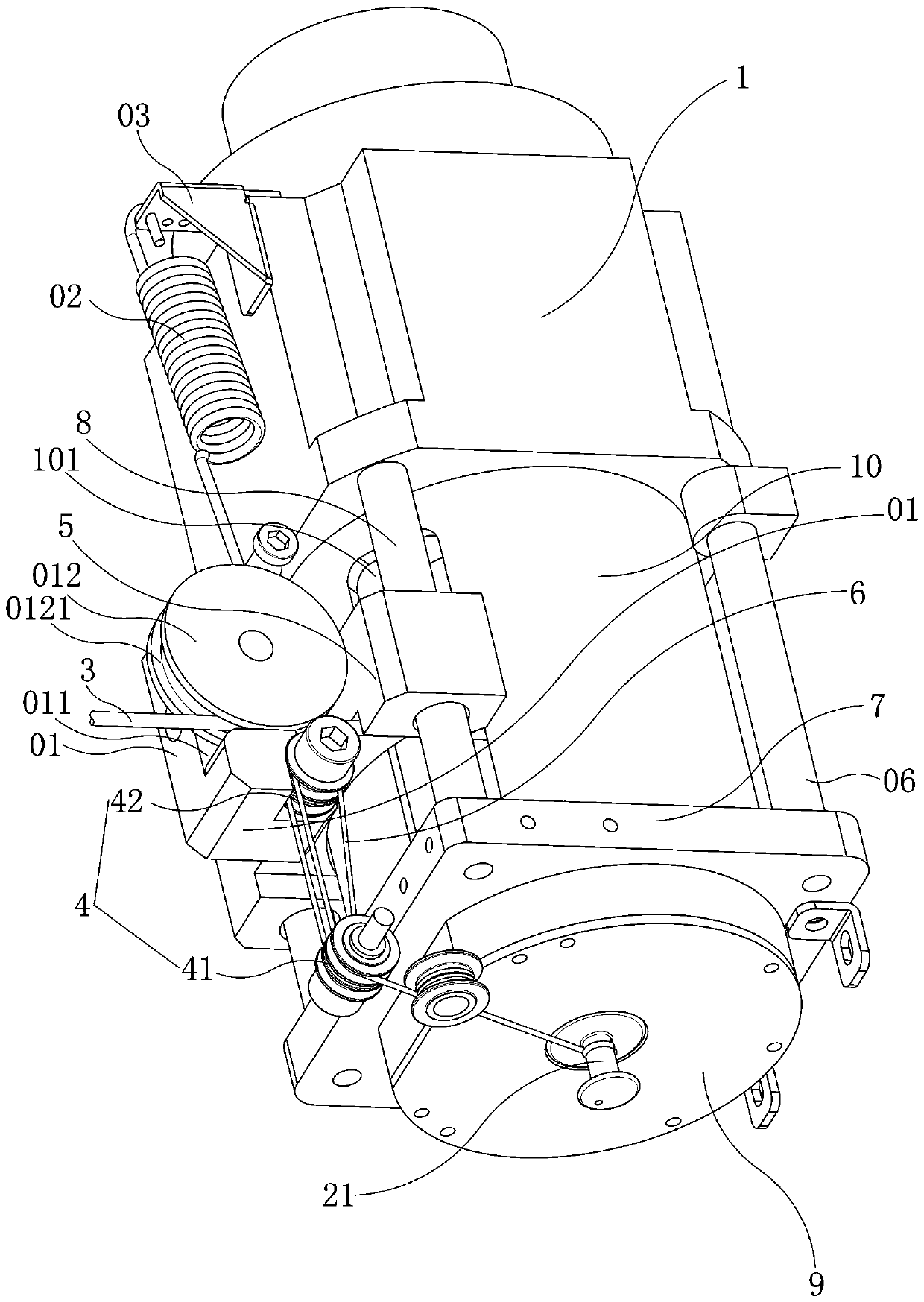
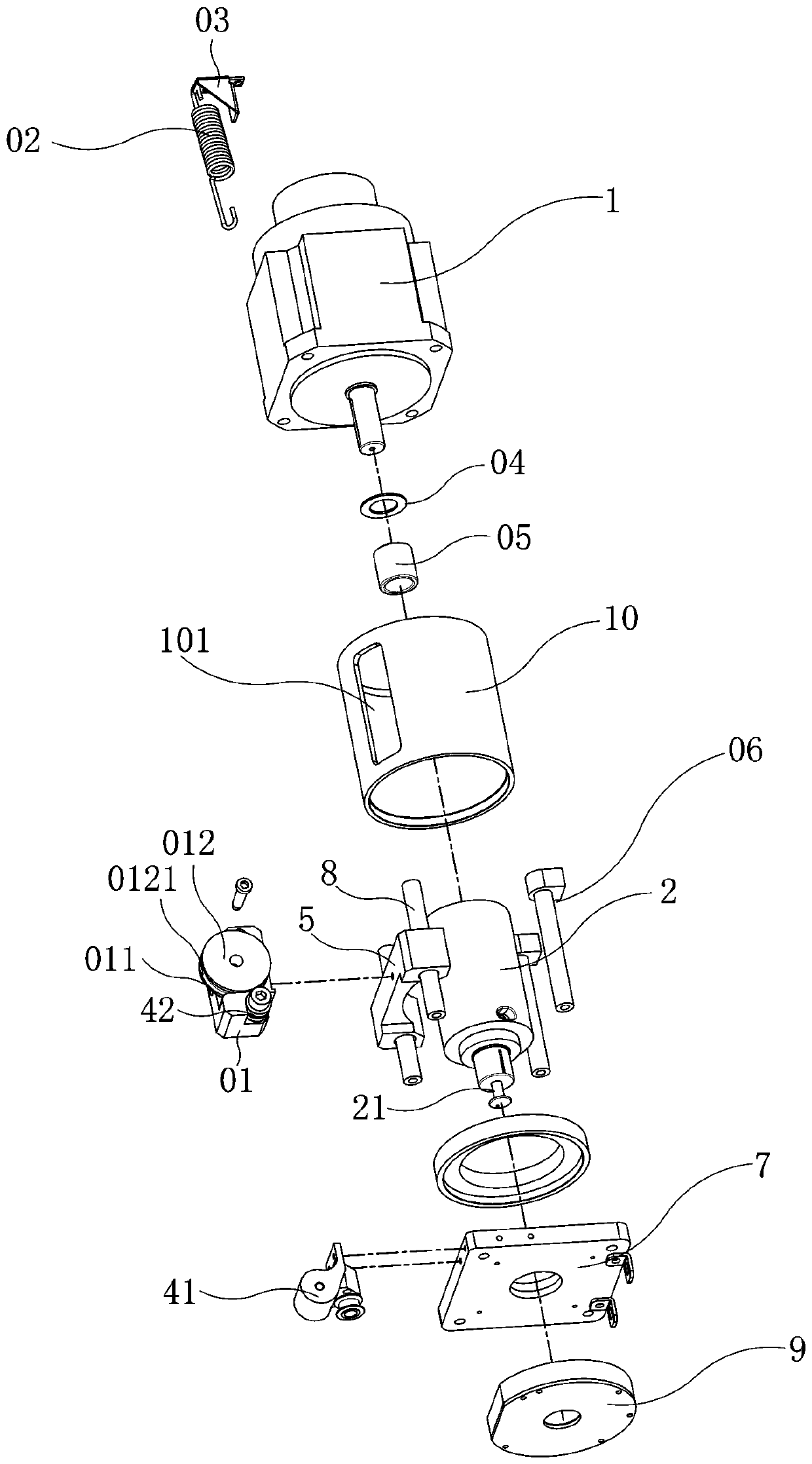
[0055] see Figure 1 to Figure 5 As shown, the present invention discloses a resistance device, comprising: a resistance source, a winch 2, a stay rope 3, a pulley block 4, a wire management mechanism, a stay wire 6 and a fixed plate 7; the output end of the resistance source is connected to one end of the winch 2 , the other end of the winch 2 is pivotally arranged on the fixed plate 7, the wire management mechanism is arranged between the fixed plate 7 and the resistance source, one end of the stay rope 3 is fixed on the winch 2, and the stay rope The other end of 3 protrudes out of the wire management mechanism, and the end of the other end of the winch 2 is protruded with ...


PUM


Abstract

The invention discloses a resistance device which comprises a resistance source, a winch, a pull rope, a pulley block, a wire arranging mechanism, a pull wire and a fixing plate. The output end of theresistance source is connected with one end of the winch; the other end of the winch is pivoted on the fixed plate; the wire arranging mechanism is arranged between the fixed plate and the resistancesource; one end of the pull rope is fixedly arranged on the winch; the other end of the pull rope convexly extends out of the wire arranging mechanism; a winding post is convexly arranged at the endpart of the other end of the winch; the pulley block comprises at least one fixed pulley and at least one movable pulley; the fixed pulley is fixedly arranged on the fixed plate; wherein the movable pulley is fixedly arranged on the wire arranging mechanism, one end of the pull wire is fixedly arranged on the winding post, the pull wire is wound among the winding post, the fixed pulley and the movable pulley, and the pull rope is linked with the wire arranging mechanism. The structure is simple, the pull rope resistance is reduced, the manufacturing cost is reduced, the manufacturing precisionrequirement is reduced, and orderly winding of the pull rope is ensured.

Description

technical field [0001] The invention relates to the technical field of motor resistance, in particular to a resistance device. Background technique [0002] The motor resistance device is an auxiliary exercise device that uses a motor to adjust the resistance. It is often used in fitness equipment. In the prior art, the known motor resistance device is mainly composed of a servo motor, a roller, a coupling and a pulley wound on the roller. The drum is pivoted on the bottom plate through the bearing seat, and the servo motor is controlled by the existing servo controller and computer, connected with the drum through a coupling, and can also rely on two transmissions of another transmission connection structure. The pulley and the belt between them realize the transmission connection between the servo motor and the drum. Pulling the pull rope can make the drum rotate around the rotating shaft. When the motor (usually a servo motor) is in the braking state, the resistance gener...

Claims


Application Information

Patent Timeline
Patent Type & Authority Applications(China)
IPC IPC(8): A63B21/005
CPCA63B21/0053A63B21/0058A63B21/153A63B21/156A63B2225/30A63B21/154
Inventor 陈岗
Owner XIAMEN LINGDONG LNTELLIGENT TECH CO LTD
Learn More