Metal liquid directional pouring method for casting and molding

A casting molding and pouring method technology is applied in the control of pouring molten metal from a casting ladle, casting equipment, metal processing equipment, etc., and can solve the problems of low degree of automation, high risk factor, and high labor intensity.

Inactive Publication Date: 2020-04-03
六安七茗道机电科技有限公司
View PDF0 Cites 1 Cited by
  • Summary
  • Abstract
  • Description
  • Claims
  • Application Information

AI Technical Summary

Problems solved by technology

[0002] Pouring refers to injecting molten metal, concrete, etc. into the mold for casting of metal parts or molding of cement boards and concrete buildings. Due to the extremely high temperature of the molten metal, the risk factor for the pouring operation of the molten metal is high, and it is always endangered. The safety of workers. At present, for the pouring of molten metal, a heat-insulated long-handled spoon is often used to pour the molten metal into the mold by manual filling. The disadvantage is that the operator is close to the molten metal, and the molten metal The heat radiated by the liquid will form a high-temperature baking for the workers. The ambient temperature perceived by the workers is high and the comfort is poor. At the same time, the risk factor is high, the degree of automation is low, and the labor intensity is high. In order to overcome the above disadvantages, it is necessary to provide a The structure is ingenious, the principle is simple, the operation is convenient and easy to use, and it is convenient to control the overturning of the container, the vertical lifting control, and the electric control molten metal pouring auxiliary method in the horizontal direction.

Method used


Image

  • Metal liquid directional pouring method for casting and molding
  • Metal liquid directional pouring method for casting and molding
  • Metal liquid directional pouring method for casting and molding

Examples


Embodiment Construction

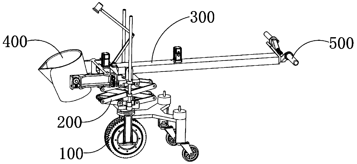
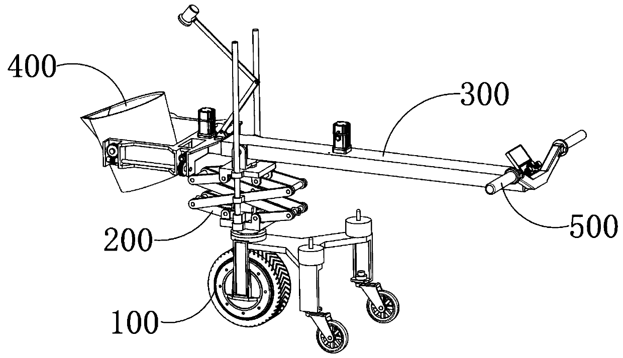
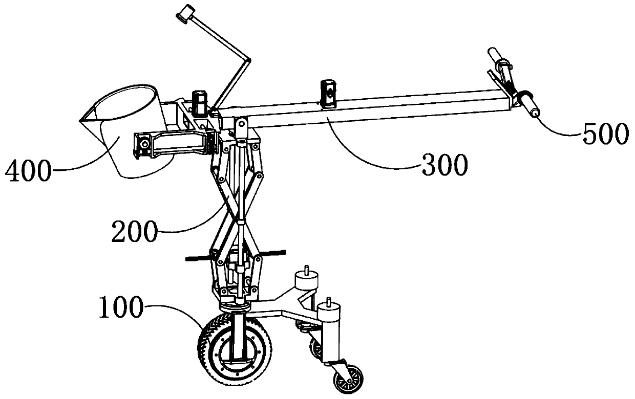
[0069] A metal liquid directional pouring method for casting molding, the steps of which are:

[0070] (1) Telescopic distance adjustment stage;

[0071] S1: first put the molten metal into the container 400, then, the operator holds the control armrest 500 with both hands, starts the telescopic mechanism 300 to gradually extend, and the distance between the telescopic end and the fixed end of the telescopic mechanism 300 increases, The barrel 400 gradually moves away from the operator until the ambient temperature felt by the operator is appropriate;

[0072] The container 400 is set on the telescopic end of the telescopic mechanism 300 and can be tilted, and the control armrest 500 is set on the fixed end of the telescopic mechanism 300 and can control the forward and backward of the traveling mechanism 100, and can control the raising and lowering of the lifting mechanism 100 , can control the elongation and shortening of the telescopic mechanism 300, can control the conta...


PUM


Abstract

The invention provides a metal liquid directional pouring method for casting and molding. The method comprises the following steps of firstly, loading the molten metal liquid into a holding barrel; secondly, holding a control handrail by an operator with two hands, starting a telescopic mechanism to be gradually extended, increasing the distance between the telescopic end and the fixed end of thetelescopic mechanism, and gradually moving the holding barrel away from the operator until the environment temperature sensed by the operator is appropriate; later, starting an advancing mechanism forrunning to drive a lifting mechanism and the telescopic mechanism to move forward to be close to a mold; then, starting the lifting mechanism to gradually rise, gradually increasing the distance between the telescopic mechanism and the advancing mechanism, and driving the holding barrel to move synchronously upwards until the holding barrel is raised above the mold; and finally, driving the holding barrel to rotate and overturn, and pouring the molten metal liquid into a pouring gate of the mold. The method has the significant advantages that overturning control over the holding barrel, lifting control in the vertical direction, and telescopic control in the horizontal direction are convenient, and the pouring efficiency and the safety are improved.

Description

technical field [0001] The invention relates to the technical field of pouring, in particular to a method for directional pouring of molten metal for casting. Background technique [0002] Pouring refers to injecting molten metal, concrete, etc. into the mold for casting of metal parts or molding of cement boards and concrete buildings. Due to the extremely high temperature of the molten metal, the risk factor for the pouring operation of the molten metal is high, and it is always endangered. The safety of workers. At present, for the pouring of molten metal, a heat-insulated long-handled spoon is often used to pour the molten metal into the mold by manual filling. The disadvantage is that the operator is close to the molten metal and the molten metal The heat radiated by the liquid will form a high-temperature baking for the workers. The ambient temperature perceived by the workers is high and the comfort is poor. At the same time, the risk factor is large, the degree of au...

Claims


Application Information

Patent Timeline
Patent Type & Authority Applications(China)
IPC IPC(8): B22D37/00
CPCB22D37/00
Inventor 胡能静费先江张冠
Owner 六安七茗道机电科技有限公司
Why Eureka
Try Eureka