Supercharge Your Innovation With Domain-Expert AI Agents!

New energy automobile speed reducer

A technology for new energy vehicles and deceleration devices, which can be applied to control devices, vehicle components, transportation and packaging, etc., and can solve problems such as inability to adjust the position of the drive shaft

Active Publication Date: 2020-04-03
TAIZHOU HONGXIN CRANKSHAFT
View PDF6 Cites 0 Cited by
  • Summary
  • Abstract
  • Description
  • Claims
  • Application Information

AI Technical Summary

Problems solved by technology

[0005] The purpose of the present invention is to provide a new energy vehicle deceleration device to solve the problem that the existing deceleration device cannot adjust the position of the transmission shaft

Method used


Image

  • New energy automobile speed reducer
  • New energy automobile speed reducer
  • New energy automobile speed reducer

Examples


Embodiment

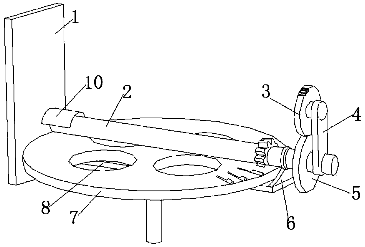
[0040] The new energy vehicle deceleration device of this embodiment includes a fixed plate 1, and a base 8 and an adjustment frame 9 are connected with bolts on the side wall of the fixed plate 1; There is a support seat 6; the output gear 7 is screwed on the base 8; one end of the transmission part 2 is screwed on the fixed plate 1 and the other end is supported on the support seat 6; the transmission part 2 meshes with the output gear 7 through the gear; on the fixed plate 1 is fixed with an adjustment cover 10 by bolts; the adjustment cover 10 is set on the outside of the transmission part 2; the fixed plate 1 is rectangular. The transmission shaft of the transmission part 2 is cylindrical, and gears are arranged on it.

[0041]One end of the transmission member 2 away from the fixed plate 1 is screwed with a connecting plate 4 and fixed with a transmission gear 5; the upper part of the connecting plate 4 is screwed with an input gear 3; the input gear 3 and the transmissi...


PUM


Abstract

A new energy automobile speed reducer comprises a fixing plate, and a base and an adjusting frame are connected to the side wall of the fixing plate through bolts; a supporting base is fixed to the upper end of the side, away from the fixing plate, of the base through bolts. The output gear is screwed on the base; one end of the transmission piece is screwed on the fixing plate, and the other endis supported on the supporting seat; a transmission part is meshed with the output gear through a gear; an adjusting cover is fixed on the fixing plate through a bolt; the adjusting cover covers the outer side of the transmission part; the supporting seat comprises a guide ring, a first adjusting seat and a second adjusting seat which are integrally formed; a supporting ring is arranged in the second adjusting seat in a penetrating manner; a screw rod is screwed in the guide ring, and one end of the first screw rod is propped against the support ring; the adjusting cover comprises a semi-cylindrical outer cover, an arc-shaped outer ring is hinged to the inner wall of the outer cover, and a buffer sheet is extruded between the outer ring and the outer cover; a third screw rod is screwed inthe outer cover; the position of the transmission shaft can be adjusted.

Description

technical field [0001] The invention relates to the technical field of automobile deceleration devices, in particular to a new energy automobile deceleration device. Background technique [0002] Most of the existing vehicle deceleration devices use gear transmission. During the meshing process of the gears, due to external forces such as vibrations and impacts, the position of the transmission shaft will deviate, resulting in deviations in the transmission, and even the gears cannot mesh normally. However, the transmission shaft of the existing gear reduction device lacks a position adjustment component, and the position of the transmission shaft cannot be adjusted; if a position deviation occurs during the transmission process, it will cause gear meshing failure and even cause equipment damage. [0003] The patent application number is CN201610399177.2, which discloses that the present invention discloses a deceleration device, including a shaft rod, a friction device, and...

Claims


Application Information

Patent Timeline
Patent Type & Authority Applications(China)
IPC IPC(8): B60K17/08
CPCB60K17/08
Inventor 徐中利
Owner TAIZHOU HONGXIN CRANKSHAFT
Features
  • R&D
  • Intellectual Property
  • Life Sciences
  • Materials
  • Tech Scout
  • Unparalleled Data Quality
  • Higher Quality Content
  • 60% Fewer Hallucinations
Learn More