A small-radius adjustable turning device for a belt conveyor
A belt conveyor, small radius technology, applied in the direction of conveyor, conveyor objects, transportation and packaging, etc., can solve the problems of poor adjustability, low efficiency, small turning angle, etc., to achieve a wide range of applications, easy to adjust efficiency. Effect
- Summary
- Abstract
- Description
- Claims
- Application Information
AI Technical Summary
Problems solved by technology
Method used
Image
Examples
Embodiment 1
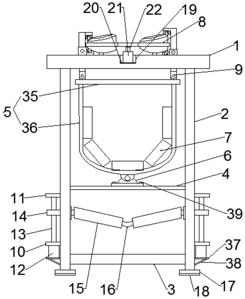
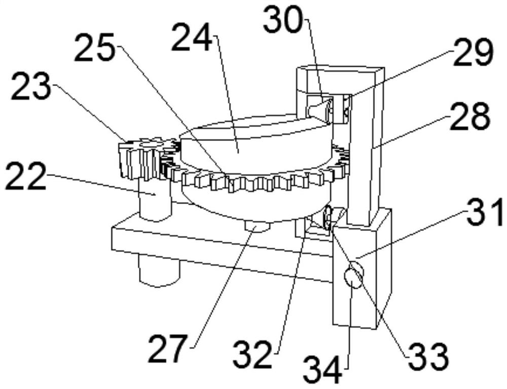
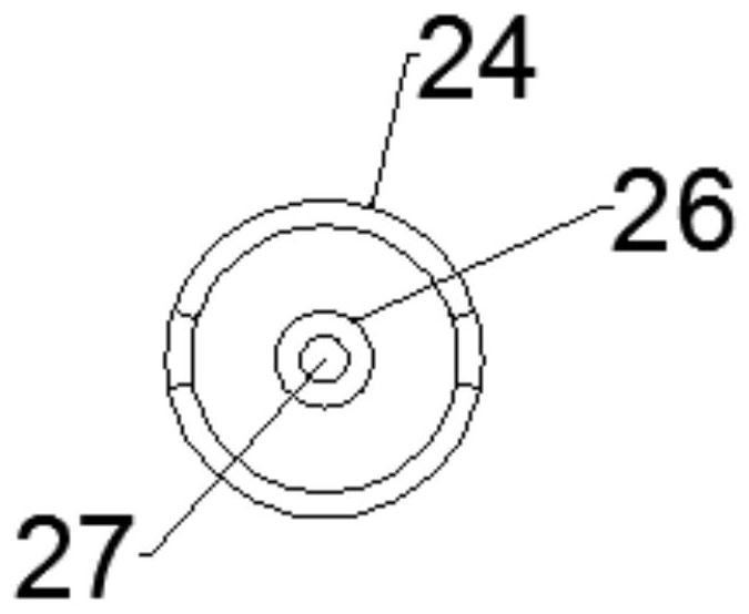
[0022] Such as Figure 1-3 As shown, the small-radius adjustable turning device of the belt conveyor according to the embodiment of the present invention includes a horizontal frame 1, and support frames 2 are arranged on both side corners of the lower end of the horizontal frame 1, and the lower end of the support frame 2 A connecting rod 3 is arranged between and below the horizontal frame 1 , and a bearing frame 4 is arranged in the middle of the supporting frame 2 and between the horizontal frame 1 and the connecting rod 3 . A roller frame 5 is arranged between the horizontal frame 1, and the middle part of the roller frame 5 is connected with the middle part of the bearing frame 4 through a movable joint 6, and the frame of the roller frame 5 is set There are a number of rollers 7, and the middle part of the upper end of the horizontal frame 1 is provided with an adjustment device 8 matched with both sides of the upper end of the roller frame 5, and the adjustment device ...
Embodiment 2
[0025] Such as Figure 1-3 As shown, the lower ends of the support frames 2 are all provided with bottom braces 17 , and the lower ends of the bottom braces 17 are all provided with anti-skid pads 18 .
[0026] Such as Figure 1-3 As shown, the lower end of the idler frame 5 has an elliptical structure, and the idler frame 5 is composed of a beam 35 and an arc beam 36, and the beam 35 and the arc beam 36 are connected through fixing bolts. One end corresponding to the moving block 14 is connected to the idler roller one 7 through a hinge. The lower end of the first motor 12 is connected to the support frame 2 through a connecting frame 37 , and a diagonal brace 38 is provided at the bottom end of the connecting frame 37 . The connecting plate under the movable connector is fixedly connected with the carrier frame 4 through connecting bolts 39 at both ends.
[0027] In order to facilitate the understanding of the above-mentioned technical solution of the present invention, t...
PUM
 Abstract
Description
Claims
Application Information
 - R&D
- Intellectual Property
- Life Sciences
- Materials
- Tech Scout
- Unparalleled Data Quality
- Higher Quality Content
- 60% Fewer Hallucinations
Browse by: Latest US Patents, China's latest patents, Technical Efficacy Thesaurus, Application Domain, Technology Topic, Popular Technical Reports.
© 2025 PatSnap. All rights reserved.Legal|Privacy policy|Modern Slavery Act Transparency Statement|Sitemap|About US| Contact US: help@patsnap.com


