
Hydraulic oil tank filter element detection method and device and hydraulic system

A technology for hydraulic oil tanks and detection methods, which is applied in the field of hydraulic systems and can solve problems such as component damage, affecting equipment operation, and hydraulic system pollution

Pending Publication Date: 2020-04-03
SANY HEAVY MACHINERY
View PDF0 Cites 2 Cited by
  • Summary
  • Abstract
  • Description
  • Claims
  • Application Information

AI Technical Summary

Problems solved by technology

This method does not take into account the characteristics of hydraulic oil, construction conditions, and operator maintenance awareness, which can easily cause pollution of the hydraulic system, resulting in damage to components, thereby affecting the operation of the equipment

Method used


Image

  • Hydraulic oil tank filter element detection method and device and hydraulic system
  • Hydraulic oil tank filter element detection method and device and hydraulic system
  • Hydraulic oil tank filter element detection method and device and hydraulic system

Examples


Embodiment Construction

[0047] In order to make the purpose, technical solutions and advantages of the embodiments of the present invention clearer, the technical solutions in the embodiments of the present invention will be clearly and completely described below in conjunction with the drawings in the embodiments of the present invention. Obviously, the described embodiments It is a part of embodiments of the present invention, but not all embodiments. The components of the embodiments of the invention generally described and illustrated in the figures herein may be arranged and designed in a variety of different configurations.

[0048] Accordingly, the following detailed description of the embodiments of the invention provided in the accompanying drawings is not intended to limit the scope of the claimed invention, but merely represents selected embodiments of the invention. Based on the embodiments of the present invention, all other embodiments obtained by persons of ordinary skill in the art wi...


PUM


Abstract

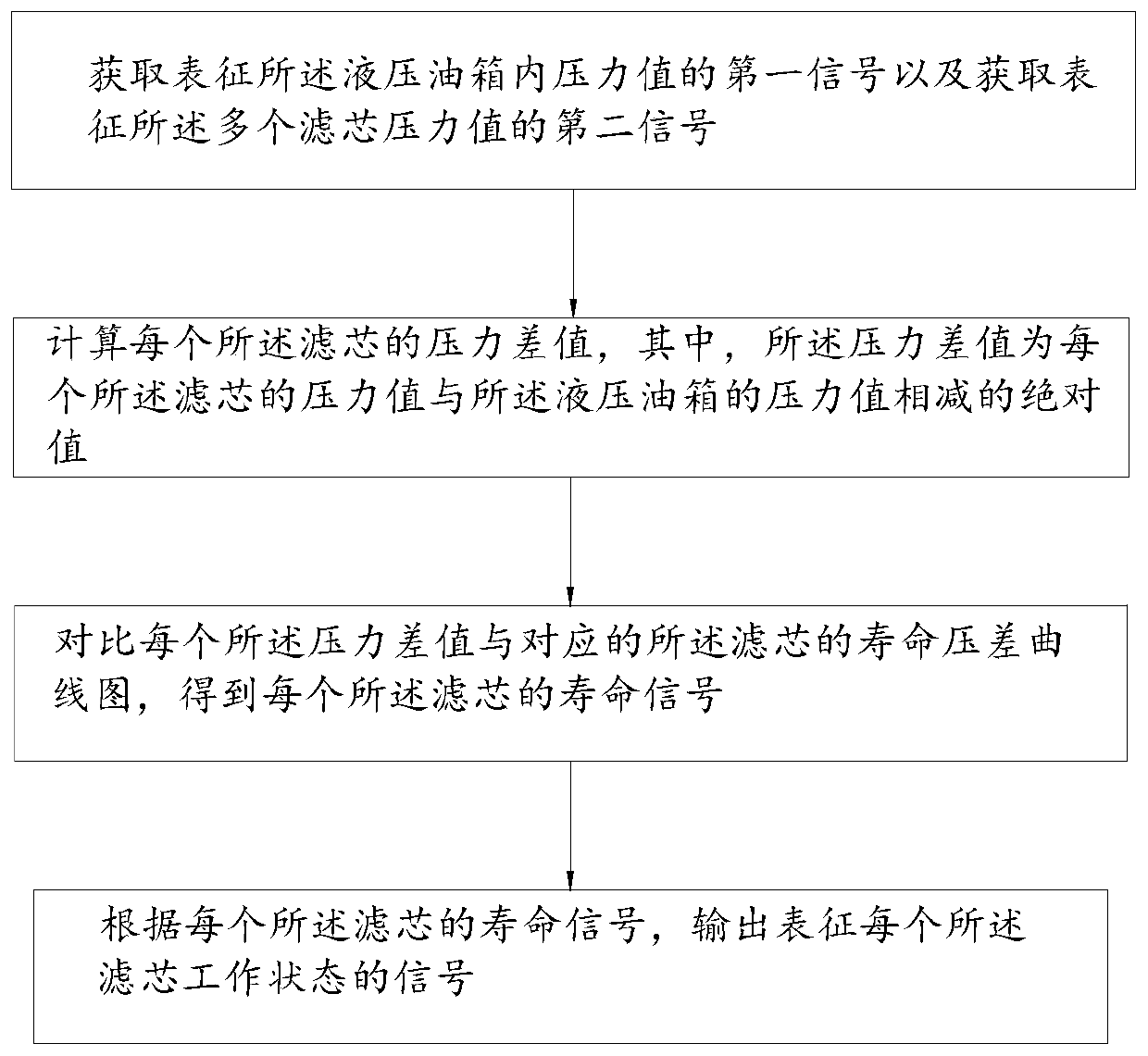
The invention relates to the field of hydraulic systems, in particular to hydraulic oil tank filter element detection method and device and a hydraulic system. The hydraulic oil tank filter element detection method is used for detecting working states of a plurality of filter elements, and the plurality of filter elements are simultaneously connected with a hydraulic oil tank, and the method comprises the following steps of, acquiring a first signal characterizing the pressure value in the hydraulic oil tank and acquiring a second signal characterizing the pressure values of the plurality of filter elements; calculating the pressure difference value of each filter element, wherein the pressure difference value is the absolute value of the pressure value of each filter element and the pressure value of the hydraulic oil tank; comparing the service life pressure difference graph of each pressure difference value and the corresponding filter element, and obtaining service life signal of each filter element; and outputting signal which characterizes the working state of each filter element. The hydraulic oil tank filter element detection method can monitor use state of each filter element in real time.

Description

technical field [0001] The invention relates to the field of hydraulic systems, in particular to a hydraulic oil tank filter element detection method, device and hydraulic system. Background technique [0002] Pollution in the hydraulic system is the main cause of hydraulic system failure. Therefore, corresponding filters are designed in each hydraulic system of construction machinery such as excavators / rotary drilling rigs. [0003] Because the filter element in the filter intercepts the pollutants in the system, its filtering effect will be reduced. In order to ensure the cleanliness of the system, the filter element needs to be replaced. In order to replace the filter element in time, the time to replace the filter element is often determined according to the service life provided by the supplier. This method does not take into account the characteristics of the hydraulic oil, the construction conditions, and the maintenance awareness of the operator, which can easily ca...

Claims


Application Information

Patent Timeline
IPC IPC(8): F15B21/041F15B19/00
CPCF15B19/005F15B21/041
Inventor 贡辉军薛庆涛
Owner SANY HEAVY MACHINERY
Learn More