A calibration system for smart tracking camera modules

A technology of intelligent tracking and calibration system, applied in stereo systems, components of TV systems, image communication, etc., can solve the problems of low calibration accuracy and poor efficiency, and achieve the effect of improving calibration accuracy, simple structure and easy implementation.

Active Publication Date: 2022-03-15
SUN YAT SEN UNIV
View PDF0 Cites 0 Cited by
  • Summary
  • Abstract
  • Description
  • Claims
  • Application Information

AI Technical Summary

Problems solved by technology

[0005] In order to solve the problems of low calibration accuracy and poor efficiency in the intelligent tracking camera module in the existing autostereoscopic display system, the present invention provides a calibration system based on the intelligent tracking camera module

Method used


Image

  • A calibration system for smart tracking camera modules
  • A calibration system for smart tracking camera modules
  • A calibration system for smart tracking camera modules

Examples


Embodiment 1

[0036] This embodiment provides a kind of calibration system for intelligent tracking camera module 2, such as Figure 7 As shown, the calibration system includes a calibration beam module 1, an intelligent tracking camera module 2, a control module 4, and a data integration module 3; the intelligent tracking camera module 2 is an internal component in an autostereoscopic display system, including a fixed tooling camera Match the spatial dimensions of the multi-degree-of-freedom detection device; the autostereoscopic display system uses a dual-camera system; wherein in this embodiment, the control module 4 and the data integration module 3 also directly use the internal components of the autostereoscopic display system without additional purchases these modules;

[0037] In the autostereoscopic display system, the position of the audience is detected in real time through the intelligent tracking camera module 2. Once the audience moves, the system will immediately adjust the p...

Embodiment 2

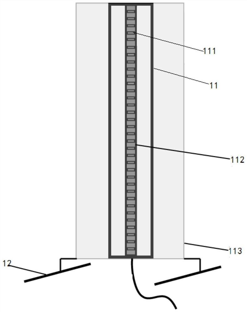
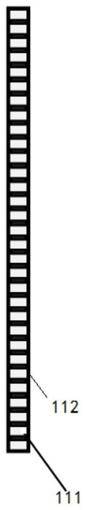
[0052] This embodiment 2 is a modification example of embodiment 1, the difference is that the light column 11 in the calibration light column module 1 is replaced by a light rod 13 with an appropriate length, such as Figure 5 As shown, it is only necessary to make it meet the requirement that it can emit extremely thin continuous light, that is, the effect obtained by the combination of the LED lamp array and the linear diffusion sheet 113 in Embodiment 1 is equivalent.

Embodiment 3

[0054] This embodiment 3 is based on the description of the calibration process for the calibration system for the intelligent tracking camera module 2 provided in embodiment 1. In this description, the LED backlight unit in the autostereoscopic display system is introduced together, but in the autostereoscopic display system The LED backlight unit does not belong to the content of the invention of the present invention; Image 6 As shown, the calibration process is as follows:

[0055] S1. System preparation: the calibration light column module 1, intelligent tracking camera module 2, data integration module 3 and control module 4 of the system enter the ready state; at this time, the calibration light column module 1 emits continuous light as a calibration image;

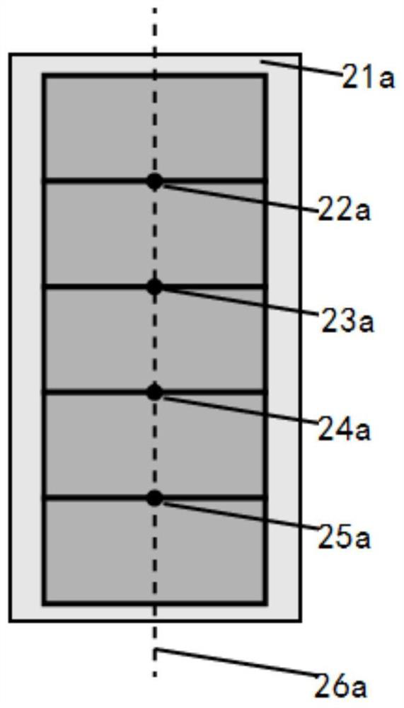
[0056] S2. The system lights up the LED backlight: the LED backlight unit of the system is composed of multiple columns of sequentially numbered LED units, and the control module 4 in the system lights up all the ...


PUM


Abstract

The invention discloses a calibration system for an intelligent tracking camera module. The calibration system includes a calibration beam module, an intelligent tracking camera module and a control module; The calibration line of the camera is automatically divided, and in each subsequent spatial position, the required spatial position data is obtained through the identification and positioning of the intelligent tracking camera module, and the control module is used to call the existing calibration line to achieve intelligence for the spatial position. Track the precise calibration of the camera module. Through the calibration system of the present invention, the global calibration of the camera module can be realized, and at the same time, the spatial dimension matching of the multi-degree-of-freedom detection device is adopted, which greatly improves the precision and accuracy of the calibration.

Description

technical field [0001] The invention relates to the technical field of stereoscopic display, in particular to a calibration system for an intelligent tracking camera module. Background technique [0002] With the continuous upgrading of new display technologies, the autostereoscopic display technology with more convenient, more comfortable and more universal working modes has gradually matured and attracted extensive attention from the industry. Autostereoscopic display technology mainly separates the existing images into left and right eye images, and through different technologies, when the observer observes the autostereoscopic display at a predetermined position along a predetermined direction, the left eye image enters the left eye, and the right eye image enters the right eye. Eyes, resulting in binocular parallax, a three-dimensional effect, and a free three-dimensional display effect. [0003] In the autostereoscopic display system, the position of the audience is d...

Claims


Application Information

Patent Timeline
Patent Type & Authority Patents(China)
IPC IPC(8): H04N13/366H04N5/232H04N17/00
CPCH04N13/366H04N17/002H04N23/60
Inventor 丁娟李焜阳李晓克陈学浩李宇周建英
Owner SUN YAT SEN UNIV
Why Eureka
Try Eureka