

Voice over Internet Protocol power saving techniques for wireless systems
A wireless device and wireless communication technology, applied in the field of wireless communication, can solve problems such as low efficiency and multi-power usage
- Summary
- Abstract
- Description
- Claims
- Application Information
AI Technical Summary
Problems solved by technology
Method used
Image

Examples
Embodiment Construction
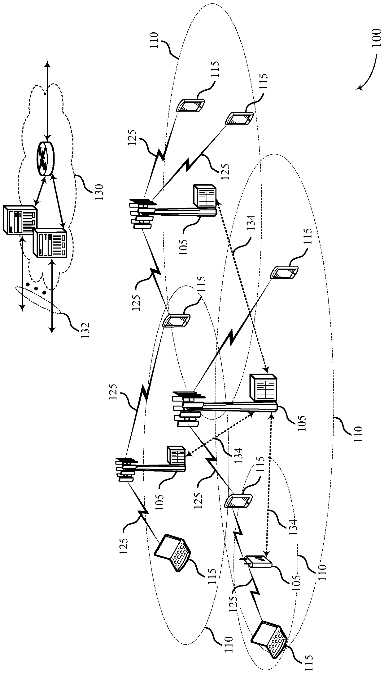
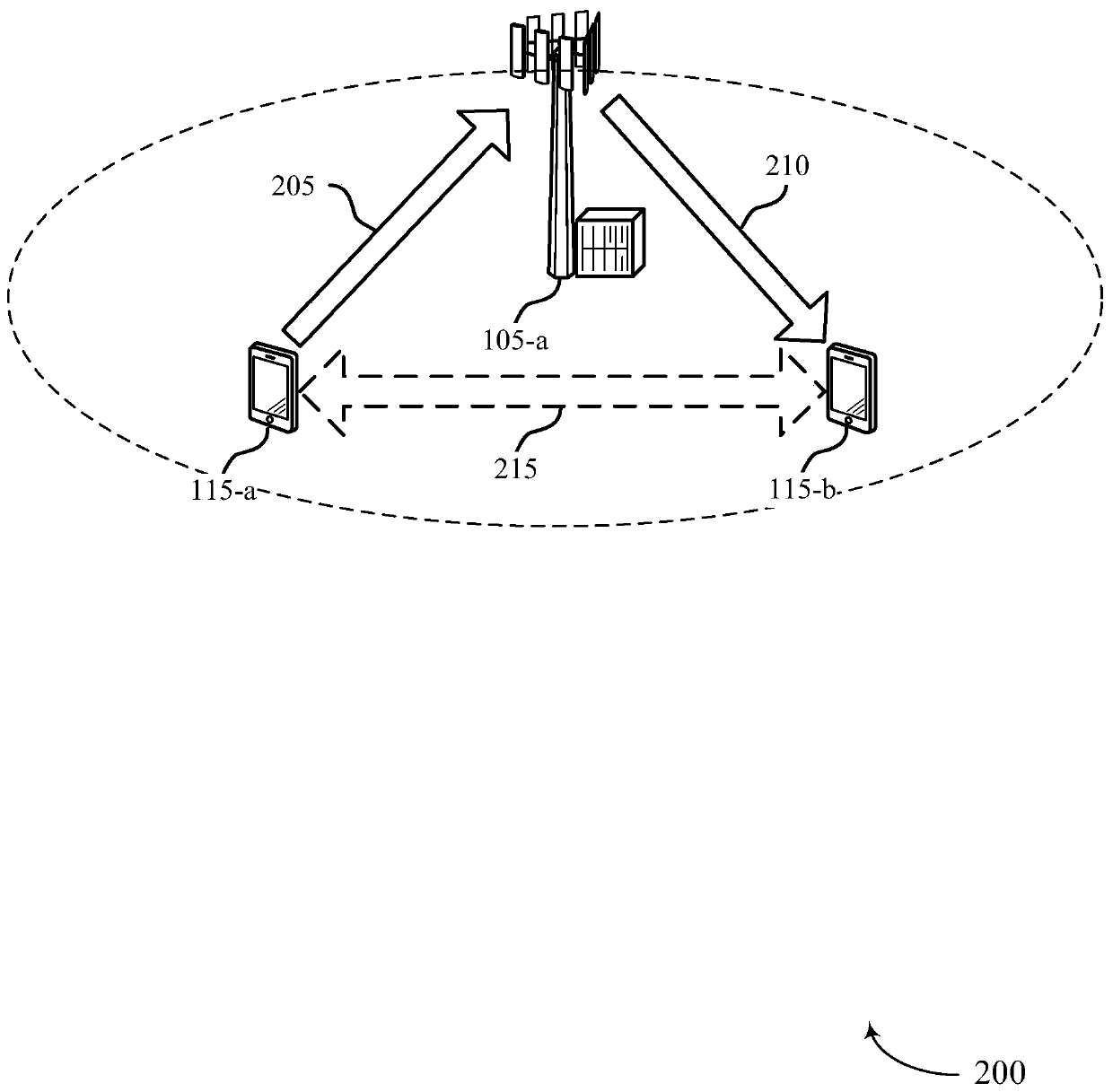
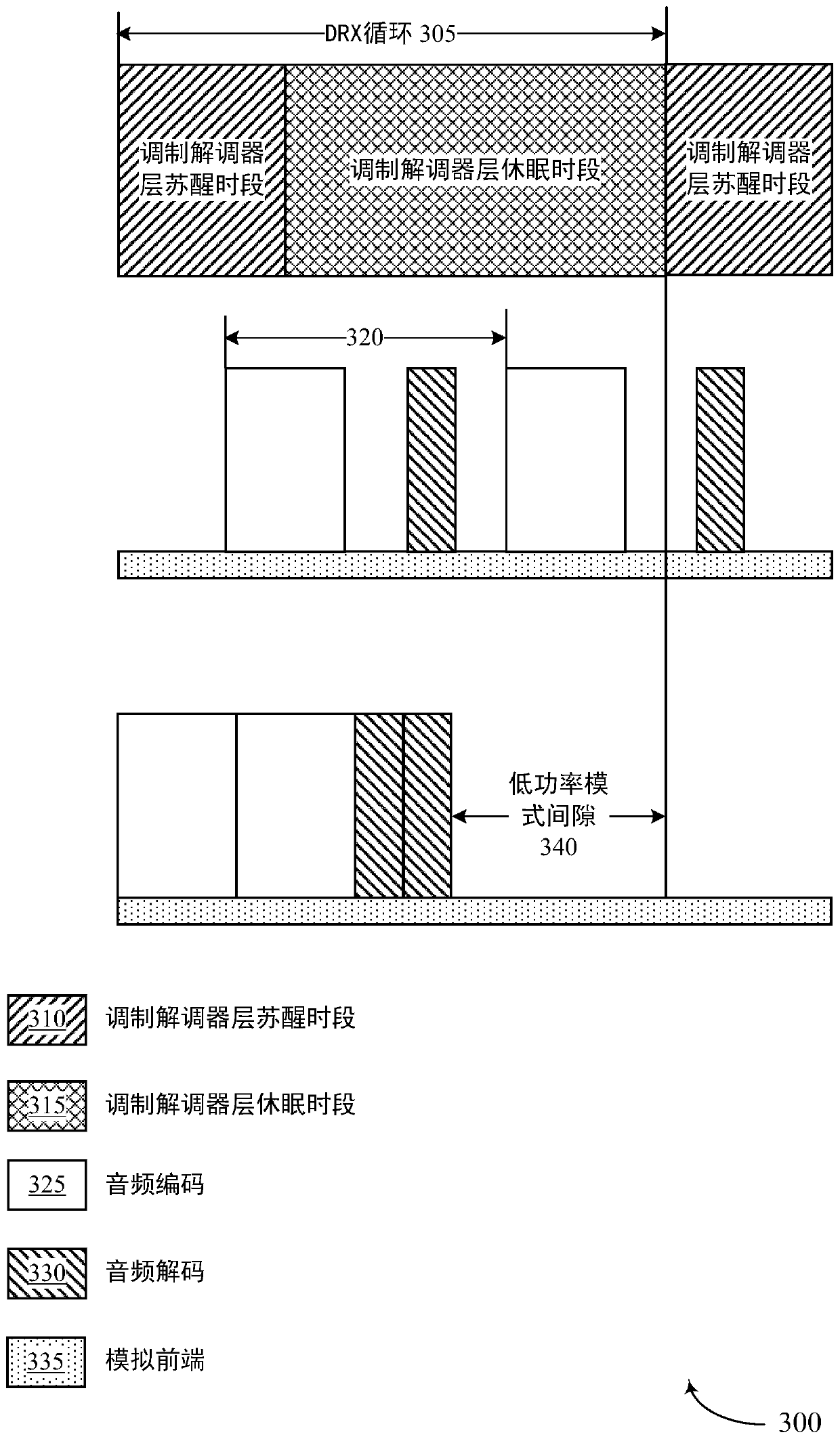
[0047] A UE may be enabled for VoLTE or other packet-based operation, enabling the UE to transmit voice information in packets (eg, over an LTE channel). A UE may include an audio layer and a packet layer. The audio layer can encode and decode voice information, and the UE can use the packet layer to send encoded voice information as packets over LTE. The audio layer may encode speech information into packets during an audio layer compression / decompression (codec) period for transmission by the packetization layer. When the voice information is ready for transmission, the audio layer may send voice packets to the packetization layer for transmission by the packetization layer. The packetization layer can be configured on a DRX cycle basis, where the UE wakes up periodically to check for pending data transfers, and then goes back to sleep after processing any pending data transfers until the next DRX cycle. The UE's audio layer and packet layer may operate asynchronously. Fo...
PUM
 Abstract
Description
Claims
Application Information