
Automatic alignment device and method

An automatic alignment and wheel set technology, which is applied in metal processing, metal processing equipment, manufacturing tools, etc., can solve the problems of increased workload, high manual participation, and reduced number of workpieces, and achieve the effect of improving operating efficiency

Active Publication Date: 2020-04-07
LOTEEM BEIJING RAIL TRANSIT TECH CO LTD
View PDF6 Cites 6 Cited by
  • Summary
  • Abstract
  • Description
  • Claims
  • Application Information

AI Technical Summary

Problems solved by technology

The main body is a gantry frame structure that can slide on the ground track. Although the main structure of the equipment will not block the traveling path of the crane hook and has little effect on the hoisting of the crane in the workshop, the main body of the equipment will occupy a part of the length, reducing the number of workshops. The number of workpieces placed on the workbench; in addition to manually moving and tightening the axle box booster arm, the operator also needs to hold the remote control to operate the gantry slide rail to move along the ground track, which increases the workload
When using multi-axis tightening, it is necessary to manually slide the power-assisted arm to feed; when aligning, the operator needs to visually measure the angular position of the workpiece hole, and then manually rotate the axle box to a certain angle to perform alignment. The data cannot be quantified and stored. The dependence is large, and the manual participation is relatively high

Method used


Image

  • Automatic alignment device and method
  • Automatic alignment device and method
  • Automatic alignment device and method

Examples


Embodiment Construction

[0045] In order to make the object, technical solution and advantages of the present invention clearer, the present invention will be further described in detail below in conjunction with the accompanying drawings and embodiments. It should be understood that the specific embodiments described here are only used to explain the present invention, not to limit the present invention. In addition, the technical features involved in the various embodiments of the present invention described below can be combined with each other as long as they do not constitute a conflict with each other.

[0046] It is easy for those skilled in the art to understand that the above descriptions are only preferred embodiments of the present invention, and are not intended to limit the present invention. Any modifications, equivalent replacements and improvements made within the spirit and principles of the present invention, etc., All should be included within the protection scope of the present inv...


PUM


Abstract

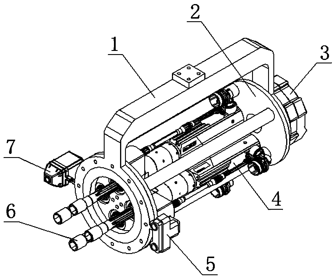
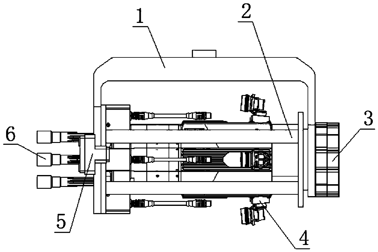
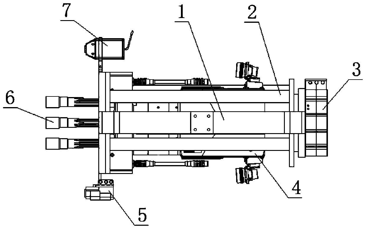
The invention discloses an automatic alignment device. The device comprises an axle box fixing and supporting hanging frame, a tightening axle fixing rotary box, an axle box servo driving motor, a tightening axle box real-time image pick-up position feedback module, a positioning device and a center control cabinet, wherein the axle box servo driving motor is connected with the axle box fixing andsupporting hanging frame and can drive the tightening axle fixing rotary box to rotate, the tightening axle box real-time image pick-up position feedback module is connected with the axle box fixingand supporting hanging frame and can shoot a hole site image of a wheel set moving under a sliding rail, the positioning device is connected with the axle box fixing and supporting hanging frame and can acquire the position information of the wheel set, and the center control cabinet matches the acquired actual hole site with the shot hole site image of the wheel set, and controls the axle box servo driving motor to act so as to realize the automatic alignment of the tightening axle fixing rotary box and the hole site of the wheel set. The invention further discloses an automatic alignment method. With the automatic alignment device of the invention adopted, addressing and positioning operation of multiple wheel sets are automatically completed, the automatic tightening operation of the wheel sets is achieved, manpower is saved, and operation efficiency and precision are improved.

Description

technical field [0001] The invention belongs to the technical field of wheel set maintenance equipment, and more specifically relates to an automatic alignment device and method. Background technique [0002] At present, the multi-axis simultaneous tightening and assembly of the CRH3 Harmony EMU wheel-to-axle end gland fastening bolts in the railway industry mainly adopts a horizontal trolley type calibration device, which is mainly composed of bottom wheels, steel structure racks, handrails, simulation The shaft end and the left and right outriggers are combined. [0003] At present, the maintenance and assembly workshops of EMU depots and EMU operating stations all over the country are mainly used for the tightening and assembly of the fastening bolts of the wheel set shaft end glands of the CRH3 Harmony EMU. There are mainly the following types: (1) Truss slide rail + Single rope suspension multi-spindle nutrunner. The way to realize it is to fix and install multiple ti...

Claims


Application Information

Patent Timeline
Patent Type & Authority Applications(China)
IPC IPC(8): B23P19/10B23P19/06B23P19/00
CPCB23P19/00B23P19/06B23P19/10
Inventor 徐娜李光耀周滔靳丹宇
Owner LOTEEM BEIJING RAIL TRANSIT TECH CO LTD
Learn More