Automatic crack pouring method and device

A joint filling and automatic technology, applied to roads, road repairs, roads, etc., can solve the problems of low efficiency of manual joint filling, large traffic accidents, and high labor costs

Active Publication Date: 2020-04-07
ZHENGZHOU UNIV
View PDF6 Cites 0 Cited by
  • Summary
  • Abstract
  • Description
  • Claims
  • Application Information

AI Technical Summary

Problems solved by technology

The efficiency of artificial joint filling is low, the closed traffic time is long, the labor cost is high, the operator is directly exposed to harmful gases for a long time,

Method used


Image

  • Automatic crack pouring method and device
  • Automatic crack pouring method and device
  • Automatic crack pouring method and device

Examples


Example Embodiment

[0087] Hereinafter, exemplary embodiments of the present disclosure will be described in detail with reference to the accompanying drawings so that those skilled in the art can easily implement them. Also, for the sake of clarity, parts unrelated to describing the exemplary embodiments are omitted from the drawings.

[0088] In the present disclosure, it should be understood that terms such as "comprising" or "having" are intended to indicate the presence of labels, numbers, steps, acts, components, parts, or combinations thereof disclosed in this specification, and are not intended to exclude a or multiple other labels, numbers, steps, acts, parts, sections, or combinations thereof may exist or be added.

[0089] In addition, it should be noted that the embodiments in the present disclosure and the tags in the embodiments may be combined with each other under the condition of no conflict. The present disclosure will be described in detail below with reference to the accompan...


PUM


Abstract

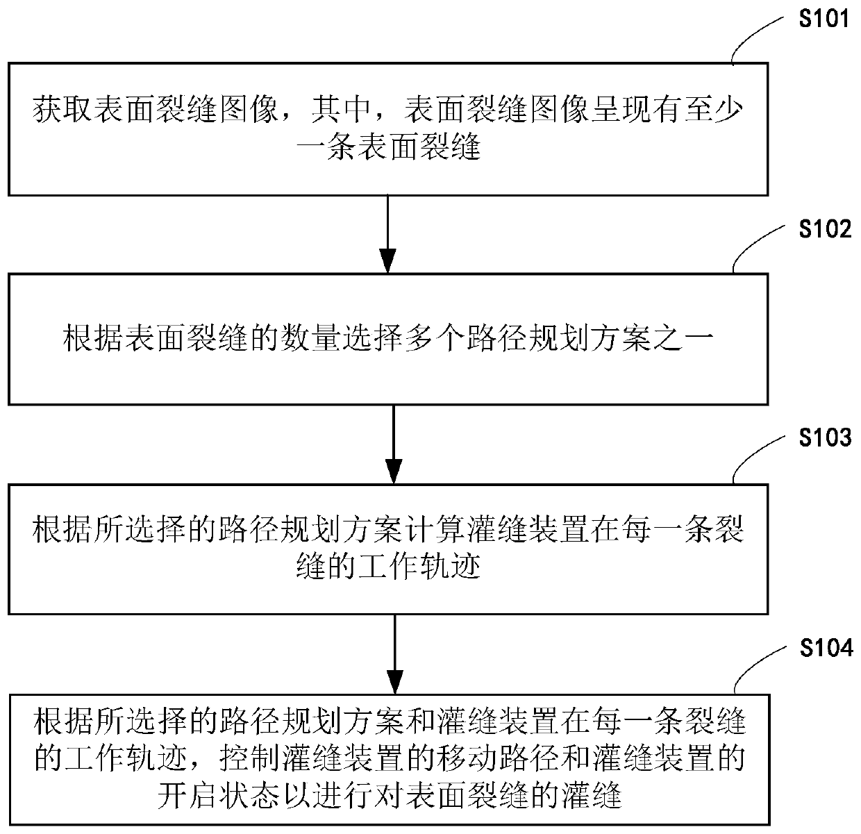
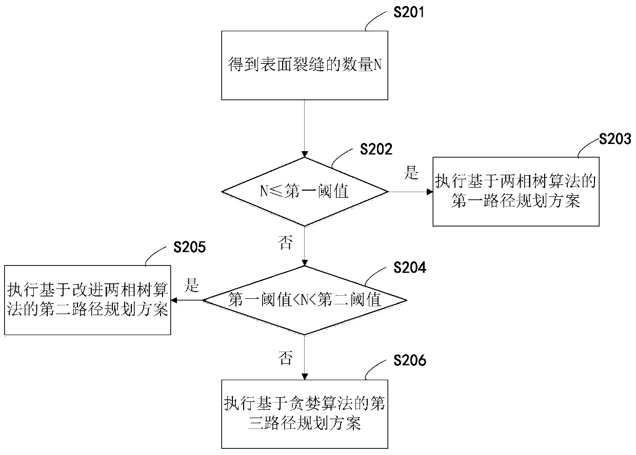
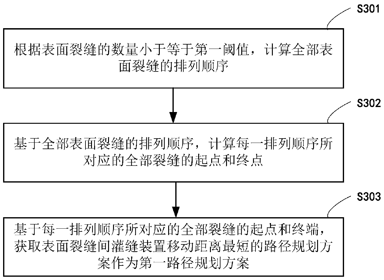
The embodiment of the invention discloses an automatic crack pouring method and device, and the method comprises the steps: obtaining a surface crack image which shows at least one surface crack; selecting one of a plurality of path planning schemes according to number of the surface cracks; calculating a working track of the crack pouring device in each crack according to the selected path planning scheme; and according to the selected path planning scheme and the working track of the crack pouring device in each crack, controlling the moving path of the crack pouring device and the opening state of the crack pouring device so as to carry out crack pouring on the surface cracks.

Description

technical field [0001] The present disclosure relates to the technical field of road maintenance, in particular to an automatic joint filling method and device. Background technique [0002] Cracks are one of the main factors threatening road safety conditions, and maintaining good road conditions is crucial to traffic safety. Pavement joint filling maintenance is a common form in road maintenance operations. For asphalt pavement, if the cracks cannot be treated in time, it will lead to serious diseases such as pumping, dislocation, network cracking, etc. For cement pavement, pavement subsidence will occur. Timely filling of joints can effectively prevent further deterioration of road surface diseases and reduce the cost of intermediate repairs. The efficiency of artificial joint filling is low, the closed traffic time is long, the labor cost is high, the operator is directly exposed to harmful gases for a long time, the probability of traffic accidents is high, and it is ...

Claims


Application Information

Patent Timeline
IPC IPC(8): E01C23/09
CPCE01C23/0973
Inventor 陆彦辉白正涵
Owner ZHENGZHOU UNIV
Why Eureka
Try Eureka