
Automobile lock

A technology of car locks and lock housings, applied in the field of operating levers, can solve problems such as complex structural solutions, achieve reliable and long-term functionality, reduce friction and wear, and reliably guide the effect

Active Publication Date: 2020-04-07
KIEKERT & KOMMANDITGES
View PDF7 Cites 0 Cited by
  • Summary
  • Abstract
  • Description
  • Claims
  • Application Information

AI Technical Summary

Problems solved by technology

[0006] The prior art is not convincing in all respects, since the guidance of the operating elements sometimes involves complex structural solutions

Method used


Image

  • Automobile lock
  • Automobile lock

Examples


Embodiment Construction

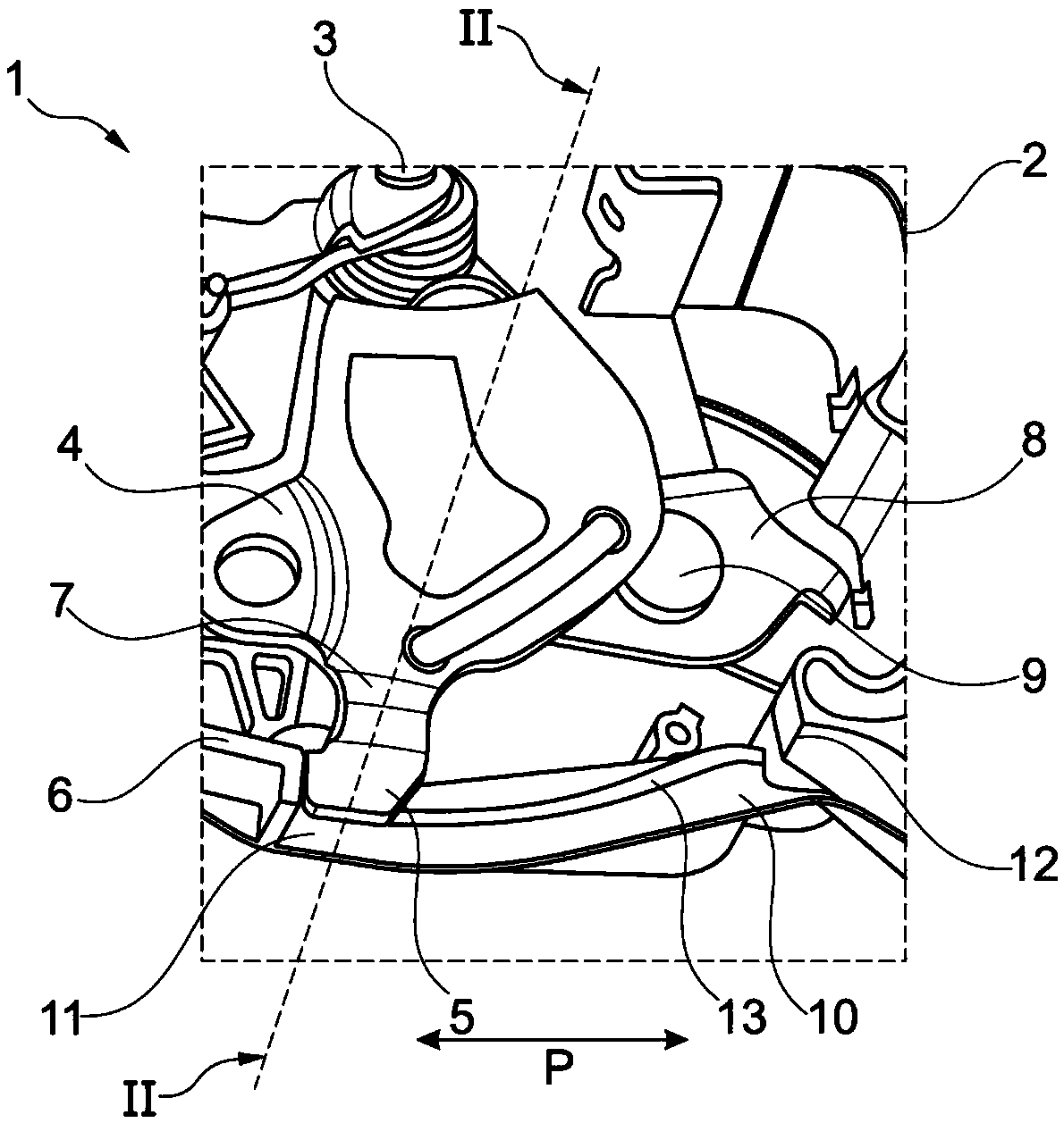
[0028] exist figure 1 A perspective view of the vehicle lock 1 and in particular a view of the lock housing 2 is shown in . In the vehicle lock 1 , an operating lever 4 is pivotably mounted on a shaft 3 . The operating lever 4 can be, for example, a latch lever or a lever for child safety. In this embodiment, the operating lever 4 is constructed in one piece and is formed as a stamped part from a sheet metal. The actuating lever 4 has a trapezoidal extension 5 which extends away from the axis 5 towards the edge 6 of the lock housing 2 . Accordingly, the extension 5 is arranged on the radial end of the operating rod 4 . A further operating element 8 is also accommodated in the lock housing 2 so as to be pivotable about an axis 9 . The operating element 8 can be, for example, an outer operating lever.

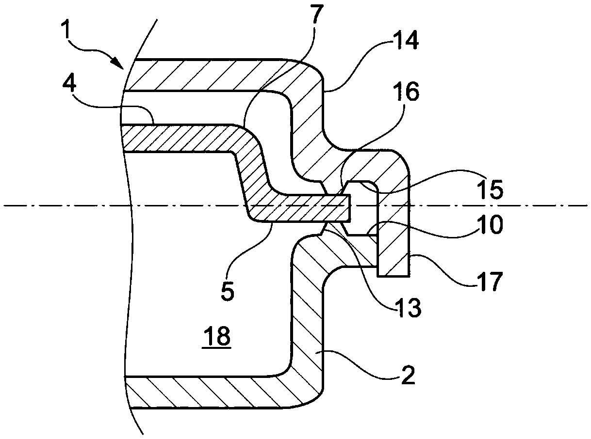
[0029] Formed on the lock housing 2 is a guide plane 10 which has stops 11 , 12 at its ends. A projection in the form of a guide rib 13 is formed approximately in the cente...


PUM


Abstract

The invention relates to an automobile lock (1). The automobile lock comprises a locking mechanism consisting of a rotary pawl and at least one pawl, a lock case (3) and a lock cover (14) at least partially closing the lock case (3), and at least one actuating element (4, 8), in particular an actuating lever (4, 8), which is pivotably mounted in the automobile lock (1), wherein the actuating element (4, 8) is provided with an extension (5), and the extension part (5) can at least partially abut against the lock case (3).

Description

technical field [0001] The invention relates to a vehicle lock with a locking mechanism comprising a rotary pawl, at least one pawl, a lock housing, a cover which at least partially closes the lock housing and at least one operating element which is pivotably mounted in the vehicle lock Especially the joystick. Background technique [0002] Locks are used in today's cars where the moving parts of the car are located. The movable part is, for example, a sliding door, a side door, a hood, a roof or a cover, to mention only a few fields of application. The lock then cooperates with a locking mechanism that is usually fixedly mounted on a lock seat on the vehicle. The locking mechanism and the other operating parts in the lock are arranged in the automobile lock for the most part in a pivotable manner. The locking mechanism is used to lock and hold moving parts in the vehicle, so that the functionality of the lock can be controlled by means of this operating element. Example...

Claims


Application Information

Patent Timeline
IPC IPC(8): E05B85/00
CPCE05B85/00E05B79/08E05B85/02
Inventor 刘玉会徐平伍建
Owner KIEKERT & KOMMANDITGES
Features
  • Generate Ideas
  • Intellectual Property
  • Life Sciences
  • Materials
  • Tech Scout
  • Unparalleled Data Quality
  • Higher Quality Content
  • 60% Fewer Hallucinations
Learn More