Foot intelligent 3D information acquisition and measurement equipment
A technology for information collection and measurement equipment, applied to foot or shoe last measurement devices, clothing, applications, etc., can solve problems such as difficulty in accurately determining the size of the target, affecting the speed and effect of collection and synthesis, and camera position setting errors, etc. To achieve the effect of improving the speed and accuracy of 3D synthesis of the foot, strong applicability, and reducing the burden of rotation
Active Publication Date: 2020-04-10
天目爱视(北京)科技有限公司
9 Cites 2 Cited by
AI-Extracted Technical Summary
Problems solved by technology
However, in practical applications, it is found that unless there is an accurate angle measurement device, the user is not sensitive to the angle, and it is difficult to determine the angle accurately; the size of the target object is difficult to accurately determine, especially in some applications where the target objec...
Method used
But, the refractive index of light-transmitting material and air is different, and part of the light will be reflected or scattered by light-transmitting material, and the light of these reflections or scattering will also be collected by image acquisition device, and form target on the image collected The reflection of the object becomes a noise image. To solve this problem, a layer of anti-reflection coating/anti-reflection coating can be set on the transparent material, so that all the light from the foot is transmitted to the bottom without being reflected, preventing noise images. However, both AR coatings and AR coatings have working wavelengths, so when using the above film systems, light sources with corresponding wavelengths should be selected. Of course, these noisy images can also be removed by subsequent image preprocessing.
[0049] Preferably, the background plate 3 is a curved plate, which can make the minimum size of the background plate 3 under the condition of obtaining the maximum background range. This makes the background plate need less space when rotating, which is beneficial to reducing the size and weight of the device, avoiding the inertia of rotation, and thus is more conducive to controlling the rotation.
[0060] The seat 6 is arranged behind the foot support device 4, so that when the user sits on the seat 6, the foot can be placed on the foot support device 4 naturally. Since each person's height and leg length are different, the position of the user's foot can be adjusted by adjusting the height of the seat at this time, so that it can be placed on the foot support device 4 naturally. The seat 6 can be adjusted by a manual adjustment device, for example, the seat 6 is connected to the base through a screw rod, and the height of the seat 6 is adjusted by rotating the screw rod. Preferably, a lifting drive device is provided, and the lifting drive device is connected to the controller in data, and the height of the lifting device is controlled by the controller, thereby adjusting the height of the seat 6 . The controller can be directly connected to the foot 3D acquisition device, for example, it can be placed near the armrest of the seat 6 to facilitate user adjustment. However, the controller can also be a mobile terminal, such as a mobile phone. In this way, through the connection between the mobile terminal and the foot 3D acquisition, the height of the seat can be controlled by controlling the lifting drive device in the mobile terminal. The mobile terminal can be operated by an operator or a user, which is more convenient and not limited by location. Of course, the controller can also be undertaken by the host computer, or by a server or cluster server. Of course, it can also be undertaken by the cloud platform through the network. These upper computers, servers, cluster servers, and cloud platforms can be shared with the upper computers, servers, cluster servers, and cloud platforms for 3D synthesi...
Abstract
The invention provides foot intelligent 3D information acquisition and measurement equipment which comprises an image acquisition device and a background plate, and is characterized in that the imageacquisition device and the background plate are oppositely arranged and synchronously rotate; the background plate and the image acquisition device are kept oppositely arranged in the rotating process, so that the background plate becomes a background pattern of an image acquired by the image acquisition device during acquisition; and the image acquisition device and the background plate rotate around feet. The mode that the background plate rotates along with a camera is added for the first time to improve the synthesis speed and the synthesis precision of a foot 3D model at the same time. Byoptimizing the size of the background plate, while the rotating burden is reduced, it is guaranteed that the foot 3D synthesis speed and the foot 3D synthesis precision can be improved at the same time.
Application Domain
Foot measurement devices
Technology Topic
Measuring equipmentEngineering +3
Image
Examples
- Experimental program(1)
Example Embodiment
[0037] Hereinafter, exemplary embodiments of the present disclosure will be described in more detail with reference to the accompanying drawings. Although exemplary embodiments of the present disclosure are shown in the drawings, it should be understood that the present disclosure can be implemented in various forms and should not be limited by the embodiments set forth herein. On the contrary, these embodiments are provided to enable a more thorough understanding of the present disclosure and to fully convey the scope of the present disclosure to those skilled in the art.
[0038] Foot 3D information collection device structure
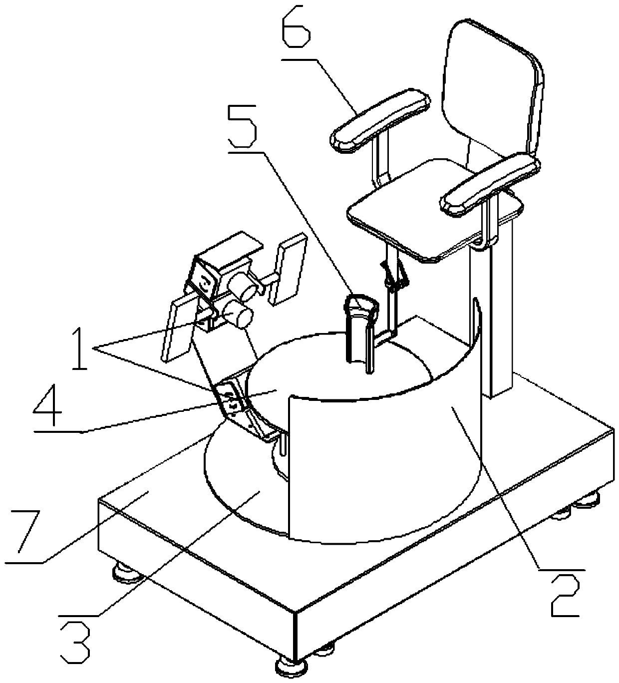
[0039] To solve the above technical problems, the present invention provides a foot 3D information collection device, such as figure 1 , Including an image capture device 1, a background plate 2, a rotating device 3, a rotating drive device, a foot support device 4, a leg support device 5, a seat 6 and a base 7.
[0040] The image acquisition device 1 and the background plate 2 are arranged opposite to each other, respectively installed at both ends of the rotating device 3, and the rotating device 3 is driven to rotate by the rotating drive device, thereby driving the image acquisition device 1 and the background plate 2 to rotate synchronously to ensure image acquisition during the acquisition process The images collected by the device 1 all use the background plate 2 as the image background. The foot support device 4 is located in the middle of the base 7 and between the image capture device 1 and the background plate 2, so that when the user's foot is placed on the foot support device 4, the image capture device 1 can capture the user's foot 360° when rotating. Several images are provided to provide image data for 3D modeling and synthesis. The image acquisition device 1 sends the acquired multiple images to a processing unit, and uses 3D synthesis modeling software in the processing unit to synthesize a 3D model of the user's foot.
[0041] The image capture device 1 includes at least two sets of cameras, one set of cameras photographs the upper part of the user's foot (foot surface) from top to bottom, and the other set of cameras photographs the lower part of the user's foot (foot sole) from the bottom up. The two sets of cameras of the image acquisition device 1 are installed on the rotating arm, and are installed on the rotating device 3 through the rotating arm, so that the rotating device 3 drives the rotating arm to rotate when rotating, so that the two sets of cameras rotate around the user’s feet to take pictures. Collect multiple sets of complete images of each position of the user's foot, including the surface of the foot, the sole of the foot, and multiple sides of the foot.
[0042] The processing unit obtains the 3D information of the user's foot according to the multiple images in the multiple sets of images. The processing unit is used to synthesize the 3D model of the target object according to the multiple images collected by the image acquisition device and the 3D synthesis algorithm to obtain the 3D information of the target object.
[0043] The processing unit can be directly arranged in the housing where the image acquisition device 1 is located, or can be connected to the image acquisition device 1 through a data cable or wirelessly. For example, an independent computer, server, cluster server, etc. can be used as the processing unit, and the image data collected by the image acquisition device 1 is transmitted to it for 3D synthesis. At the same time, the data of the image acquisition device 1 can also be transmitted to a cloud platform, and the powerful computing power of the cloud platform can be used for 3D synthesis.
[0044] The rotating device 3 is a turntable, which is installed on the base. One end of the turntable is connected with a rotating arm, and the other end is connected with the background plate 2. The center of the turntable is provided with a hole so that the foot support device 4 can be fixedly connected to the base through the hole. Therefore, when the turntable rotates, the foot support device 4 is not affected. Of course, the rotating device 3 may also have other forms, such as a rotating arm with a hole in the middle.
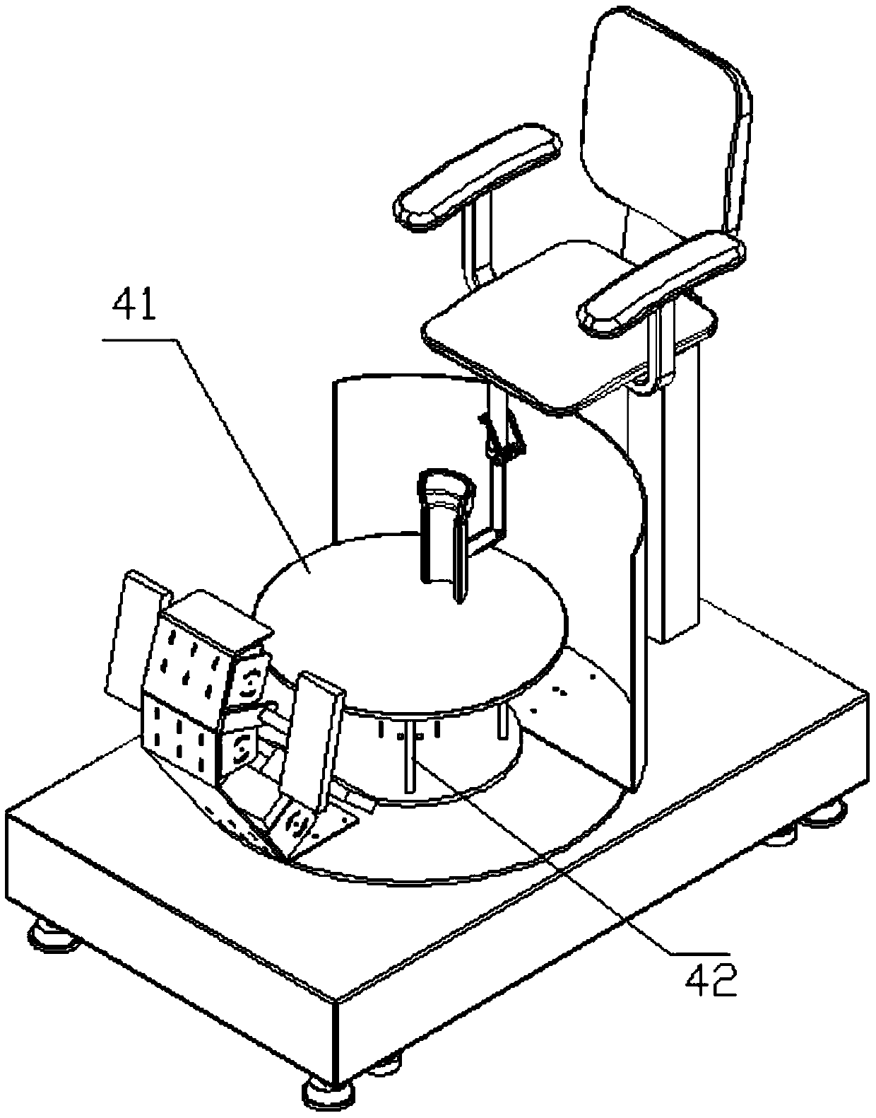
[0045] The foot support device 4 includes a support plate 41 and a pillar 42, such as figure 2 , Wherein the supporting plate 41 is made of a light-transmitting material, for example, a glass plate or a lens resin plate. The support plate 41 may also be partially made of light-transmitting material, for example, the area where the user's foot is placed in the middle is made of light-transmitting material. The light-transmitting material also has a foot area mark, which instructs the user to place the foot in the center of the light-transmitting material. Preferably, an additional light source can be used to indicate: in the user's preparation stage, an additional light source is used to project the foot area on the light-transmitting material to help the user place the foot in the correct position. But at the beginning of the acquisition, the light source is turned off. This can prevent the mark of the foot area from affecting subsequent 3D synthetic modeling. In another method, the device also has a display, which is connected to the camera and can display the foot images taken by the camera. At the same time, the mark of the foot area is displayed on the display, and the image of the foot collected by the camera overlaps these marks on the display. By observing the display, the position of the foot can be adjusted to align the foot with the mark.
[0046] However, the refractive index of the light-transmitting material is different from that of the air. Some light will be reflected or scattered by the light-transmitting material. The reflected or scattered light will also be collected by the image acquisition device, forming a reflection of the target on the collected image. Become a noisy image. To solve this problem, a layer of anti-reflection film/anti-reflection film can be arranged on the transparent material, so that all the light from the foot can be transmitted to the bottom without being reflected, so as to prevent the appearance of noise images. However, both anti-reflection and anti-reflection coatings have operating wavelengths, so when using the above-mentioned film systems, a light source of the corresponding wavelength should be selected. Of course, these noisy images can also be removed by subsequent image preprocessing.
[0047] The background board 2 is all solid colors, or most (main body) are solid colors. In particular, it can be a white board or a black board, and the specific color can be selected according to the main color of the target object. The background board 2 is usually a flat panel, preferably a curved panel, such as a concave panel, a convex panel, a spherical panel, and even in some application scenarios, it can be a background panel 2 with a wavy surface; it can also be spliced with multiple shapes For example, the plates can be spliced with three planes, and the whole is concave, or flat and curved surfaces can be spliced. In addition to the shape of the surface of the background plate 2 can be changed, the shape of its edge can also be selected as required. Normally, it is linear, which constitutes a rectangular plate. But in some applications, the edges can be curved.
[0048] Calculation of the size of the background board
[0049] Preferably, the background panel 3 is a curved panel, which can minimize the projection size of the background panel 3 when the maximum background range is obtained. This makes the background board need less space when it rotates, which is conducive to reducing the size of the device, reducing the weight of the device, and avoiding rotational inertia, which is more conducive to controlling the rotation.
[0050] Regardless of the surface shape and edge shape of the background board 3, the projection is performed in the direction perpendicular to the surface to be photographed, and the length W in the horizontal direction of the projection shape 1 , The vertical length of the projection shape W 2 Determined by the following conditions:
[0051]
[0052]
[0053] Where d 1 Is the horizontal length of the imaging element, d 2 Is the vertical length of the imaging element, T is the vertical distance from the sensor element of the image capture device to the background plate along the optical axis, f is the focal length of the image capture device, A 1 , A 2 Is the experience coefficient.
[0054] After a lot of experiments, it is preferred that A 1 1.04, A 2 1.04; more preferred 2> A 1 1.1, 2> A 2 1.1.
[0055] In some application scenarios, the edge of the background board is non-linear, resulting in non-linear edges of the projected graphics after projection. Measure W at different positions 1 , W 2 Are different, so W 1 , W 2 Not easy to determine. Therefore, you can take 3-5 points on the opposite sides of the background plate 3, measure the linear distance between the two points, and then take the measured average value as W in the above conditions. 1 , W 2.
[0056] The following table is the experimental control results:
[0057] Experimental conditions:
[0058] Collection object: human foot
[0059] Experience coefficient Synthesis time Synthesis accuracy A 1 = 1.2, A 2 = 1.2
[0060] The seat 6 is arranged behind the foot support device 4 so that when the user sits on the seat 6, the feet can be naturally placed on the foot support device 4. Since each person has a different height and leg length, the position of the user's foot can be adjusted by adjusting the height of the seat at this time, so that it can be placed on the foot support device 4 naturally. The seat 6 can be adjusted by a manual adjustment device, for example, the seat 6 is connected to the base through a screw rod, and the height of the seat 6 is adjusted by rotating the screw rod. Preferably, there is a lifting driving device, which is data-connected with the controller, and the height of the lifting device is controlled by the controller, thereby adjusting the height of the seat 6. The controller can be directly connected to the foot 3D acquisition device, for example, it can be prevented from near the armrest of the seat 6 to facilitate user adjustment. But the controller can also be a mobile terminal, such as a mobile phone. In this way, through the mobile terminal and the foot 3D collection connection, the height of the seat can be controlled by controlling the lifting driving device in the mobile terminal. The mobile terminal can be operated by an operator or a user, which is more convenient and is not restricted by location. Of course, the controller can also be borne by the host computer, or by the server or cluster server. Of course, it can also be borne by the cloud platform through the network. These host computers, servers, cluster servers, and cloud platforms can be shared with host computers, servers, cluster servers, and cloud platforms that perform 3D synthesis processing, that is, complete the dual functions of control and 3D synthesis.
[0061] The seat 6 is provided with a leg support device 5 for limiting the user's legs, ensuring a fixed foot position during the collection process, and preventing the user's foot from moving relative to the foot support device due to leg movement. The leg support device 5 may be a semi-cylindrical groove.
[0062] The light source can be arranged on the image acquisition device 1 or on the rotating arm. The light source can be an LED light source or a smart light source, that is, the light source parameters are automatically adjusted according to the target object and ambient light. Generally, the light source is distributed in a dispersed manner around the lens of the image capture device, for example, the light source is a ring LED light around the lens. In particular, a soft light device, such as a soft light housing, can be arranged on the light path of the light source. Or directly use the LED surface light source, not only the light is softer, but also the light is more uniform. More preferably, an OLED light source can be used, which is smaller in size, has softer light, and has flexible characteristics that can be attached to curved surfaces.
[0063] In order to facilitate the measurement of the actual size of the user's foot, a marker point with known coordinates can be set at a position that can be photographed by the image acquisition device 1. For example, it can be provided on the foot support device 4. By collecting marker points and combining their coordinates, the absolute size of the 3D synthetic model is obtained.
[0064] During the use of the foot 3D information collection device, the user sits on the seat 6 with the legs placed on the leg support device 5 and restricted by it. The user's foot is naturally placed on the light-transmitting material part of the foot support device 4. The rotation driving device drives the rotation device 3 to rotate, thereby driving the image acquisition device 1 and the background plate 2 to rotate together in synchronization. Whenever the image acquisition device 1 rotates a certain distance, the upper and lower two sets of cameras of the image acquisition device 1 collect an image of the target object. When the rotation device 3 completes one revolution, the image acquisition device 1 also rotates around the user's foot. . At this time, the image acquisition device 1 can acquire a group of 360° images of the target. Since the image acquisition device 1 may include multiple sets of cameras, each set of cameras will obtain a corresponding set of images. The above image acquisition process can be completed synchronously with the rotation. At this time, the camera shutter needs to be set, and a higher shutter is required. You can also rotate for a certain distance and stop, then continue to rotate after shooting, and so on. The above multiple sets of images are transferred to the processing unit, and a 3D synthetic modeling algorithm is used in the processing unit to construct a 3D model of the user's foot in a state where the user's feet are naturally not stressed.
[0065] After collecting the image of the user's foot in the natural state, the user can be made to stand and repeat the above shooting process, so as to obtain the image of the user's foot in the daily stress state, and finally construct the 3D of the user's foot in the daily stress state model.
[0066] Optimize the collection position of the image collection device
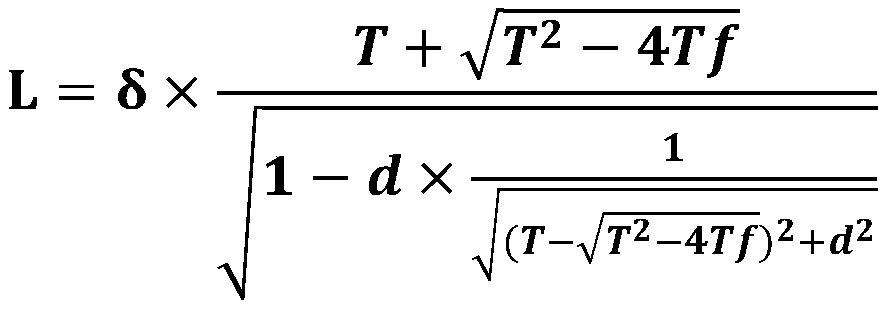
[0067] According to a large number of experiments, the collected separation distance preferably satisfies the following empirical formula:
[0068] When performing 3D acquisition, two adjacent acquisition positions of the image acquisition device 1 meet the following conditions:
[0069]
[0070] Where L is the linear distance of the optical center of the image acquisition device 1 at two adjacent acquisition positions; f is the focal length of the image acquisition device 1; d is the rectangular length or width of the photosensitive element (CCD) of the image acquisition device 1; T is the image The distance from the photosensitive element of the collection device 1 to the surface of the target along the optical axis; δ is the adjustment coefficient, δ <0.5955.
[0071] When the above two positions are along the length direction of the photosensitive element of the image capture device 1, d takes the rectangular length; when the above two positions are along the width direction of the photosensitive element of the image capture device 1, d takes the width of the rectangle.
[0072] When the image capture device 1 is at any one of the two positions, the distance from the photosensitive element to the surface of the target along the optical axis is taken as T. In addition to this method, in another case, L is A n , A n+1 The linear distance between the optical centers of the two image acquisition devices 1 and A n , A n+1 Two adjacent image acquisition devices 1 A n-1 , A n+2 Two image capture devices 1 and A n , A n+1 The distances from the photosensitive elements of the two image acquisition devices 1 to the surface of the target along the optical axis are respectively T n-1 , T n , T n+1 , T n+2 , T=(T n-1 +T n +T n+1 +T n+2 )/4. Of course, it is not limited to 4 adjacent positions, and more positions can also be used for average calculation.
[0073] L should be the linear distance between the optical centers of the two image capture devices 1, but because the position of the optical centers of the image capture devices is not easy to determine in some cases, the center of the photosensitive element of the image capture device 1 can also be used in some cases , The geometric center of the image acquisition device 1, the axis center of the image acquisition device 1 and the pan/tilt (or platform, bracket), and the center of the proximal or distal surface of the lens are replaced by experiments. Within the acceptable range.
[0074] Generally, in the prior art, parameters such as object size and field of view are used as a method for estimating the position of the camera, and the positional relationship between two cameras is also expressed by angle. Since the angle is not easy to measure in actual use, it is more inconvenient in actual use. Also, the size of the object will change with the change of the measured object. For example, after collecting the 3D information of an adult's head, and then collecting the head of a child, the head size needs to be re-measured and recalculated. The above-mentioned inconvenient measurement and multiple re-measurements will cause measurement errors, resulting in errors in the estimation of the camera position. Based on a large amount of experimental data, this solution provides the empirical conditions that the camera position needs to meet, which not only avoids measuring angles that are difficult to accurately measure, but also does not need to directly measure the size of the object. In the empirical conditions, d and f are fixed parameters of the camera. When purchasing the camera and lens, the manufacturer will give the corresponding parameters without measurement. And T is only a straight line distance, which can be easily measured by traditional measurement methods, such as rulers and laser rangefinders. Therefore, the empirical formula of the present invention makes the preparation process convenient and quick, and at the same time improves the accuracy of the arrangement of the camera position, so that the camera can be set in an optimized position, thereby taking into account the 3D synthesis accuracy and speed at the same time. Specific experiments See below for data.
[0075] Experiments were carried out using the device of the present invention, and the following experimental results were obtained.
[0076] Camera: MER-2000-19U3M/C
[0077] Lens: OPT-C1616-10M
[0078]
[0079] From the above experimental results and a lot of experimental experience, it can be concluded that the value of δ should satisfy δ <0.5955, some 3D models can already be synthesized at this time. Although some of them cannot be synthesized automatically, it is acceptable if the requirements are not high, and the unsynthesized part can be made up manually or by changing the algorithm. Especially the value of δ satisfies δ When <0.453, it can best balance the synthesis effect and synthesis time; in order to obtain a better synthesis effect, you can choose δ <0.338, the synthesis time will increase at this time, but the synthesis quality is better. When δ is 0.7053, it can no longer be synthesized. However, it should be noted here that the above scope is only the best embodiment and does not constitute a limitation on the protection scope.
[0080] And from the above experiments, it can be seen that for the determination of the camera's shooting position, only the camera parameters (focal length f, CCD size) and the distance T between the camera CCD and the surface of the object can be obtained according to the above formula, which makes the equipment design and It becomes easy when debugging. Since the camera parameters (focal length f, CCD size) are determined when the camera is purchased, and will be marked in the product description, it is easy to obtain. Therefore, the camera position can be easily calculated according to the above formula, without the need for tedious field angle measurement and object size measurement. Especially in some occasions, it is necessary to replace the camera lens, then the method of the present invention can directly replace the lens to calculate the conventional parameter f to obtain the camera position; similarly, when different objects are collected, the measurement of the object size is also More cumbersome. With the method of the present invention, there is no need to measure the size of the object, and the camera position can be determined more conveniently. In addition, the camera position determined by the present invention can take into account the synthesis time and the synthesis effect. Therefore, the above empirical condition is one of the invention points of the present invention.
[0081] The above data is only obtained from experiments to verify the conditions of the formula, and does not limit the invention. Even without these data, it does not affect the objectivity of the formula. Those skilled in the art can adjust the equipment parameters and step details as needed to perform experiments, and obtain other data that also meets the conditions of the formula.
[0082] Production of foot appendages
[0083] In order to make shoes suitable for the user's foot shape, a 3D model can be synthesized by collecting 3D information of the user's foot, so as to design or select a suitable shoe according to the size of the foot 3D model. The above-mentioned production should refer to the size of the 3D model of the user's foot under natural stress-free state and the size of the 3D model of the user's foot under daily stress.
[0084] In addition to the production of shoes, prostheses can also be produced based on the above data. For example, the patient's foot needs to be amputated, and the 3D model of the foot is collected and constructed before the amputation, so that a prosthetic of a suitable size can be provided for the foot after the amputation.
[0085] In addition, any processing and production that can be performed using foot data are possible, and the present invention is not limited.
[0086] The rotational movement of the present invention is that during the acquisition process, the previous position acquisition plane and the next position acquisition plane cross instead of being parallel, or the optical axis of the image acquisition device at the previous position crosses the optical axis of the next position image acquisition position. Instead of parallel. In other words, the movement of the acquisition area of the image acquisition device around or partly around the target object can be regarded as the relative rotation of the two. Although the examples of the present invention enumerate more rotational motions with tracks, it is understandable that as long as non-parallel motion occurs between the acquisition area of the image acquisition device and the target, it is all in the category of rotation, and the present invention can be used. Qualification. The protection scope of the present invention is not limited to the orbital rotation in the embodiment.
[0087] The adjacent acquisition positions in the present invention refer to two adjacent positions on the moving track where the acquisition action occurs when the image acquisition device moves relative to the target. This is usually easy to understand for image capture device movement. However, when the target object moves to cause the two to move relatively, at this time, the movement of the target object should be converted into the target object's immobility according to the relativity of the movement, and the image acquisition device moves. At this time, measure the two adjacent positions of the image acquisition device where the acquisition action occurs in the transformed movement track.
[0088] The aforementioned target object, target object, and object all represent objects for which three-dimensional information is pre-acquired. It can be a physical object, or a combination of multiple objects. For example, it can be a head, a hand, etc. The three-dimensional information of the target includes a three-dimensional image, a three-dimensional point cloud, a three-dimensional grid, a local three-dimensional feature, a three-dimensional size, and all parameters with a three-dimensional feature of the target. The so-called three-dimensional in the present invention refers to having XYZ three-direction information, especially depth information, which is essentially different from only two-dimensional plane information. It is also essentially different from the definitions called three-dimensional, panoramic, holographic, and three-dimensional, but actually only include two-dimensional information, especially depth information.
[0089] The collection area mentioned in the present invention refers to the range that an image collection device (such as a camera) can shoot. The image acquisition device in the present invention can be CCD, CMOS, camera, video camera, industrial camera, monitor, camera, mobile phone, tablet, notebook, mobile terminal, wearable device, smart glasses, smart watch, smart bracelet and belt All devices with image capture function.
[0090] The 3D information of multiple regions of the target obtained in the above embodiment can be used for comparison, for example, for identification. First, use the solution of the present invention to obtain the 3D information of the human face and iris, and store it in the server as standard data. When in use, such as when identity authentication is required for payment, door opening, etc., the 3D acquisition device can be used to collect and obtain 3D information of the human face and iris again, and compare it with the standard data. If the comparison is successful, the next step is allowed. One step. It is understandable that this kind of comparison can also be used for the identification of fixed assets such as antiques and artworks, that is, first obtain 3D information of multiple areas of antiques and artworks as standard data, and obtain 3D information of multiple areas again when authentication is required. Information and compare with standard data to identify authenticity.
[0091] In the instructions provided here, a lot of specific details are explained. However, it can be understood that the embodiments of the present invention can be practiced without these specific details. In some instances, well-known methods, structures and technologies are not shown in detail, so as not to obscure the understanding of this specification.
[0092] Similarly, it should be understood that in order to simplify the present disclosure and help understand one or more of the various inventive aspects, in the above description of the exemplary embodiments of the present invention, the various features of the present invention are sometimes grouped together into a single embodiment, Figure, or its description. However, the disclosed method should not be interpreted as reflecting the intention that the claimed invention requires more features than those explicitly stated in each claim. More precisely, as reflected in the following claims, the inventive aspect lies in less than all the features of a single embodiment disclosed previously. Therefore, the claims following the specific embodiment are thus explicitly incorporated into the specific embodiment, wherein each claim itself serves as a separate embodiment of the present invention.
[0093] Those skilled in the art can understand that it is possible to adaptively change the modules in the device in the embodiment and set them in one or more devices different from the embodiment. The modules or units or components in the embodiments can be combined into one module or unit or component, and in addition, they can be divided into multiple sub-modules or sub-units or sub-components. Except that at least some of such features and/or processes or units are mutually exclusive, any combination can be used to compare all features disclosed in this specification (including the accompanying claims, abstract and drawings) and any method or methods disclosed in this manner or All the processes or units of the equipment are combined. Unless expressly stated otherwise, each feature disclosed in this specification (including the accompanying claims, abstract and drawings) may be replaced by an alternative feature providing the same, equivalent or similar purpose.
[0094] In addition, those skilled in the art can understand that although some embodiments herein include certain features included in other embodiments but not other features, the combination of features of different embodiments means that they fall within the scope of the present invention. And form different embodiments. For example, in the claims, any one of the claimed embodiments can be used in any combination.
[0095] The various component embodiments of the present invention may be implemented by hardware, or by software modules running on one or more processors, or by their combination. Those skilled in the art should understand that a microprocessor or a digital signal processor (DSP) may be used in practice to implement some or all of the functions based on some or all of the components in the device according to the embodiments of the present invention. The present invention can also be implemented as a device or device program (for example, a computer program and a computer program product) for executing part or all of the methods described herein. Such a program for realizing the present invention may be stored on a computer-readable medium, or may have the form of one or more signals. Such signals can be downloaded from Internet websites, or provided on carrier signals, or provided in any other form.
[0096] It should be noted that the above-mentioned embodiments illustrate rather than limit the present invention, and those skilled in the art can design alternative embodiments without departing from the scope of the appended claims. In the claims, any reference signs placed between parentheses should not be constructed as a limitation to the claims. The word "comprising" does not exclude the presence of elements or steps not listed in the claims. The word "a" or "an" preceding an element does not exclude the presence of multiple such elements. The invention can be implemented by means of hardware comprising several different elements and by means of a suitably programmed computer. In the unit claims enumerating several devices, several of these devices may be embodied in the same hardware item. The use of the words first, second, and third does not indicate any order. These words can be interpreted as names.
[0097] So far, those skilled in the art should realize that although several exemplary embodiments of the present invention have been illustrated and described in detail herein, they can still be disclosed according to the present invention without departing from the spirit and scope of the present invention. The content directly determines or derives many other variations or modifications that conform to the principles of the present invention. Therefore, the scope of the present invention should be understood and deemed to cover all these other variations or modifications.
PUM


Description & Claims & Application Information
We can also present the details of the Description, Claims and Application information to help users get a comprehensive understanding of the technical details of the patent, such as background art, summary of invention, brief description of drawings, description of embodiments, and other original content. On the other hand, users can also determine the specific scope of protection of the technology through the list of claims; as well as understand the changes in the life cycle of the technology with the presentation of the patent timeline. Login to view more.
Similar technology patents
Yacht monitoring device and system
Owner:DALIAN JIAOTONG UNIVERSITY
Barrel-shaped composite structural member overall molding method capable of achieving easy demolding
Owner:DALIAN UNIV OF TECH
Indoor personnel evacuation simulation method based on hybrid space
Owner:HUAZHONG NORMAL UNIV
Eyemask feedback type sleep-assisting system with micro-current stimulation
Owner:GUANGDONG UNIV OF TECH
Hand intelligent 3D information acquisition and measurement device
ActiveCN111351447Asynthesis speedImprove synthesis accuracy
Owner:天目爱视(北京)科技有限公司
Color separation spraying method for partial finish paint
Owner:CRRC TANGSHAN CO LTD +1
Fast and efficient semiconductor laser cladding device with wide light beam and adjustable powder feeding angle
ActiveCN110144583AIncrease single pass cladding areaReduce the burden of rotation
Owner:HUAZHONG UNIV OF SCI & TECH
Classification and recommendation of technical efficacy words
- Reduce the burden of rotation
- Improve synthesis accuracy
Fast and efficient semiconductor laser cladding device with wide light beam and adjustable powder feeding angle
ActiveCN110144583AIncrease single pass cladding areaReduce the burden of rotation
Owner:HUAZHONG UNIV OF SCI & TECH
Hand intelligent 3D information acquisition and measurement device
ActiveCN111351447Asynthesis speedImprove synthesis accuracy
Owner:天目爱视(北京)科技有限公司