Food pushing device for dysphagia patient

A technology for patients with difficulty in swallowing, applied in the field of medical care, can solve the problems of secondary injury to patients, too fast pushing, choking of food materials, etc., and achieves the effect of good installation and fastening, avoiding choking phenomenon, and good flexibility.

Inactive Publication Date: 2020-04-10
杭州蒂尔佳仪器有限公司
View PDF0 Cites 1 Cited by
  • Summary
  • Abstract
  • Description
  • Claims
  • Application Information

AI Technical Summary

Problems solved by technology

[0003] When the existing food pusher is in use, the user pours food into the food pusher, and then inserts the device into the human body through a catheter, and then presses the handle to push the internal piston to move to push the food. Enter the body for feeding, but in actual operation, the medical staff controls the rate of pushing the food by

Method used


Image

  • Food pushing device for dysphagia patient
  • Food pushing device for dysphagia patient
  • Food pushing device for dysphagia patient

Examples


Example Embodiment

[0020] Example 1

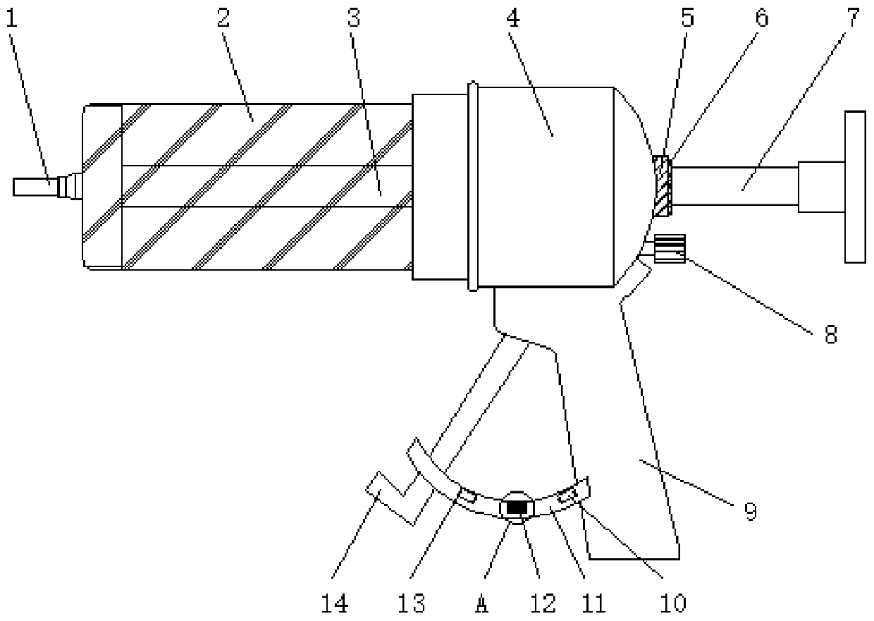
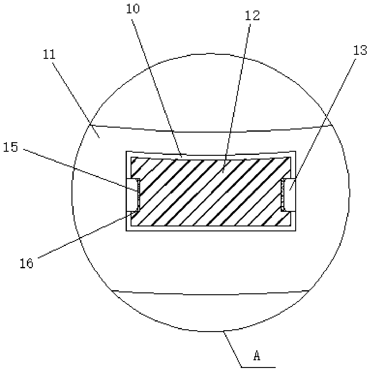
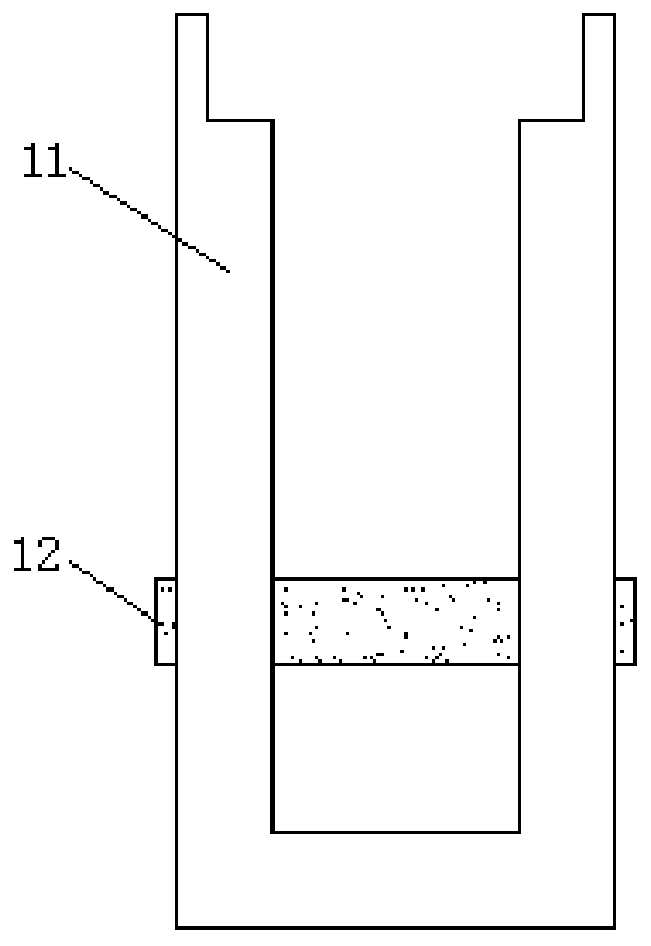
[0021] see Figure 1 to Figure 3 , the present invention provides a technical solution: a food pusher for patients with dysphagia, including a handle 4, a handle 9 is arranged at the bottom of the handle 4, one end of the handle 9 is connected to a movable handle 14 through a shaft rotation, and a limit frame 11 is arranged on the outer side of the movable handle 14 , the designed limit frame 11 is installed on the surface of the present invention, thereby facilitating the installation and support of the limit plate 12, one end of the limit frame 11 is fixed on the surface of the handle 9, and the side wall of the limit frame 11 is symmetrically provided with jacks 10 , the inside of the socket 10 runs through the limiting plate 12, and through the designed limiting plate 12, the limiting plate 12 inserts the range of motion of 14 into the socket 10 according to the actual movement, and then plays a role of limiting, effectively avoiding the traditional Due...

Example Embodiment

[0022] Example 2

[0023] see Figure 1 to Figure 4 , the present invention provides a technical solution: a food pusher for patients with dysphagia, including a handle 4, a handle 9 is arranged at the bottom of the handle 4, one end of the handle 9 is connected to a movable handle 14 through a shaft rotation, and a limit frame 11 is arranged on the outer side of the movable handle 14 , the designed limit frame 11 is installed on the surface of the present invention, thereby facilitating the installation and support of the limit plate 12, one end of the limit frame 11 is fixed on the surface of the handle 9, and the side wall of the limit frame 11 is symmetrically provided with jacks 10 , the inside of the socket 10 runs through the limiting plate 12, and through the designed limiting plate 12, the limiting plate 12 inserts the range of motion of 14 into the socket 10 according to the actual movement, and then plays a role of limiting, effectively avoiding the traditional Due...


PUM


Abstract

The invention discloses a food pushing device for a dysphagia patient. The food pushing device comprises a handle shank; and a handle is arranged at the bottom of the handle shank. One end of the handle is rotationally connected with a movable handle through a shaft rod. A limiting frame is arranged on the outer side of the movable handle; one end of the limiting frame is fixed to the surface of the handle; inserting holes are symmetrically formed in the side walls of the limiting frame; and limiting plates penetrate the interiors of the inserting holes and the longitudinal sections of the limiting plates have rectangular structures. According to the invention, the limiting frame is designed and is installed on the surface of the pushing device, the limiting plates are mounted and supported conveniently; and with the designed limiting plates, the limiting plates are inserted into the inserting holes according to an actual moving range of the movable handle to realize limiting, so thata choking phenomenon caused by excessive feeding because the extrusion range cannot be controlled traditionally is effectively avoided.

Description

technical field [0001] The invention belongs to the technical field of medical care, and in particular relates to a food pusher for patients with dysphagia. Background technique [0002] The food pusher is mainly a nursing device that puts the food into the food storage tube, and then sends it into the body of the bedridden patient by pushing it, so as to achieve feeding. [0003] When the existing food pusher is in use, the user pours food into the food pusher, and then inserts the device into the human body through a catheter, and then presses the handle to push the internal piston to move to push the food. Enter the body for feeding, but in actual operation, the medical staff controls the rate of pushing the food by pressing the rotation arc of the handle, so it often cannot control the optimal feeding rate, and often pushes too fast or the arc is too high If it is too large, it will lead to the problem of choking and causing secondary harm to the patient. For this reaso...

Claims


Application Information

Patent Timeline
IPC IPC(8): A61J9/00A61J15/00
CPCA61J9/00A61J15/0011A61J15/0026
Inventor 来文怡
Owner 杭州蒂尔佳仪器有限公司
Why Eureka
Try Eureka