Device and method for removing ions in water of cooling water tank

A technology of cooling water tanks and ion devices, which is applied in the direction of light water/sewage treatment, etc., can solve the problems of inability to effectively reduce the ion concentration and the increase of ion concentration, so as to meet the needs of equipment operation, reduce ion concentration, and reduce ion concentration in cooling water. Effect

Inactive Publication Date: 2020-04-10
NORTHEAST LIGHT ALLOY CO LTD
View PDF3 Cites 0 Cited by
  • Summary
  • Abstract
  • Description
  • Claims
  • Application Information

AI Technical Summary

Problems solved by technology

[0003] The purpose of the present invention is to solve the problem that after the ACS6000 rectifier and inverter device has been running for a period of time, the ion concentration in the cooling water will increase, and the ion concentration cannot be effectively reduced, resulting in shutdown waiting and affecting the start-up rate.

Method used


Image

  • Device and method for removing ions in water of cooling water tank
  • Device and method for removing ions in water of cooling water tank
  • Device and method for removing ions in water of cooling water tank

Examples


specific Embodiment approach 1

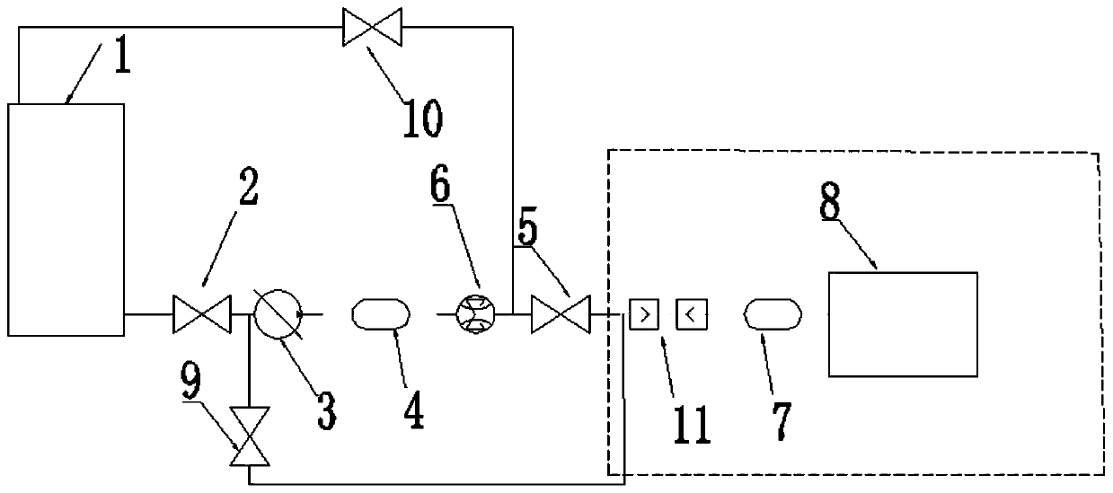
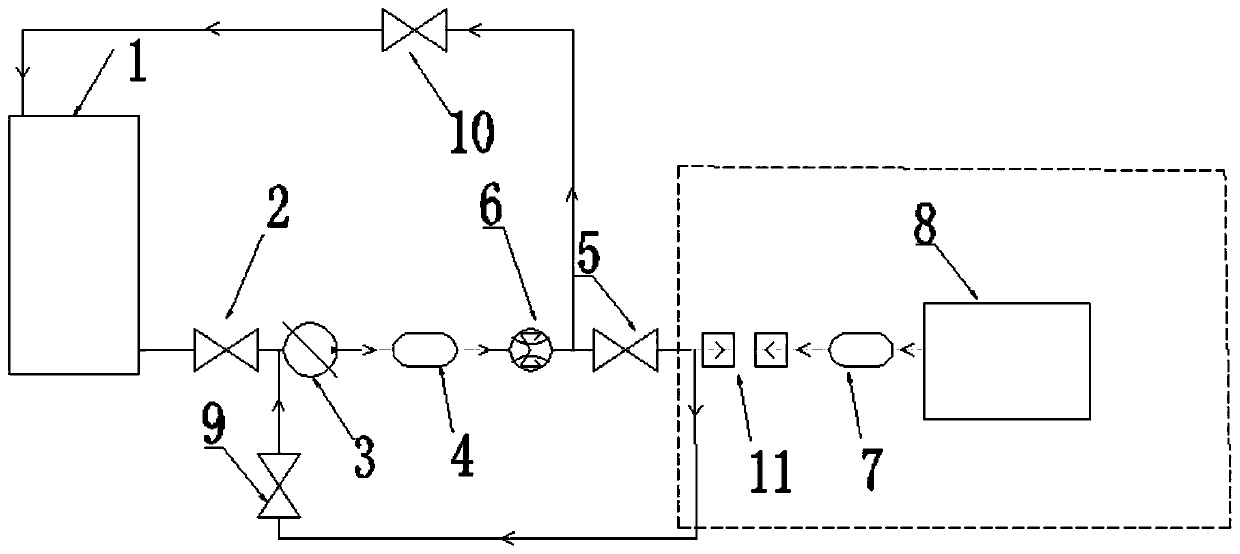
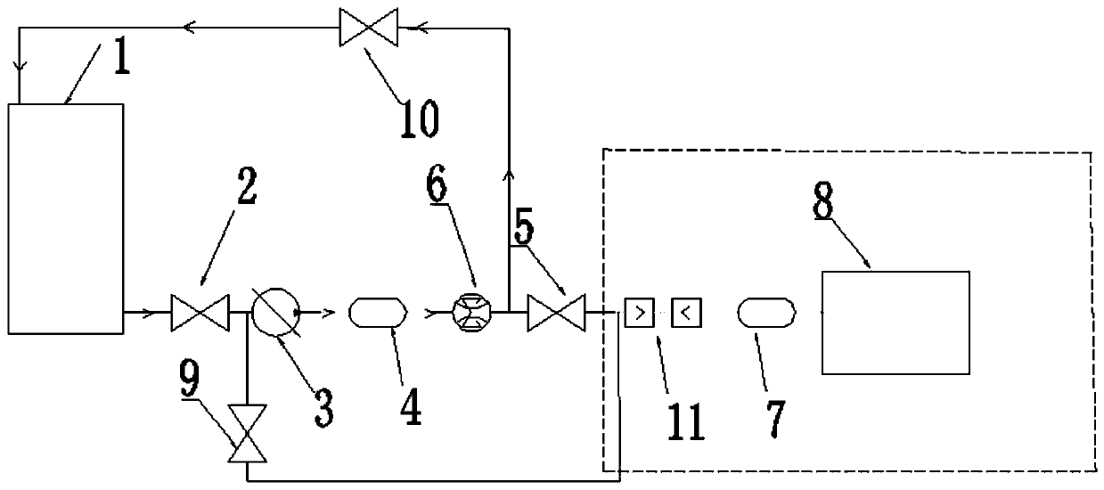
[0017] Specific implementation mode one: combine Figure 1 to Figure 4 Describe the embodiment of this city, a water ion removal device for a cooling water tank in this embodiment, which includes a water tank 1, a power pump 3, a deionization tank 4, an ion concentration display meter 6, a deionization tank 2 7 and a cooling water tank 8 ;

[0018] The water outlet of the water tank 1 is connected with the water inlet of the ball valve one 2, the water outlet of the ball valve one 2 is connected with the water inlet of the power pump 3, the water outlet of the power pump 3 is connected with the water inlet of the deionization tank one 4, and the deionization tank one 4 The water outlet is connected to the water inlet of the ion concentration display meter 6, the water outlet of the ion concentration display meter 6 is connected to the water inlet of the ball valve 2 5, the water outlet of the ball valve 2 5 is connected to the water inlet of the ion tank 2 7, and the deionizat...

specific Embodiment approach 2

[0020] Specific implementation mode two: combination Figure 1 to Figure 4 Describe the implementation mode in this city. The difference between this implementation mode and the specific embodiment one is that the power pump 3 is a DC pump and adopts 24DC direct current. Others are the same as in the first embodiment.

specific Embodiment approach 3

[0021] Specific implementation mode three: combination Figure 1 to Figure 4 Describe the embodiment of this city, the difference between this embodiment and the specific embodiment one is: the pumping flow rate of the power pump 3 is 20L / min. Others are the same as in the first embodiment.

[0022] Specific implementation mode four: combination Figure 1 to Figure 4 Describe the embodiment of this city. The difference between this embodiment and the first embodiment is that the water tank is divided into a water inlet chamber and a water outlet chamber. Others are the same as in the first embodiment.

[0023] Specific implementation mode five: combination Figure 1 to Figure 4 Describe this city's implementation mode, the difference of this implementation mode and specific embodiment one is: be provided with water absorption filter, liquid level gauge, quick connector and hand valve in the water tank. Others are the same as in the first embodiment.

[0024] Specific impl...


PUM


Abstract

The invention discloses a device and a method for removing ions in water of a cooling water tank, relates to a cooling device, and aims to solve the problems that after an ACS6000 rectifying and inverting device operates for a period of time, the ion concentration in cooling water can be increased, and the shutdown waiting influence on the startup rate cannot be effectively reduced. The device comprises a water tank, a power pump, a deionization tank, an ion concentration display meter, connecting pipelines for all parts and pipeline quick plug connectors for all parts. The water tank is provided with an opening at the lower position, a quick plug connector is arranged and connected with a water suction port of a power pump quick plug connector, a water outlet quick plug connector is connected with an inlet of the deionization tank, and an outlet of the deionization tank is directly connected with an oil tank upper gland inlet. The device is suitable for a 3950 hot roughing mill ACS6000 power supply system, and is applied to deionization of cooling water of a rectifying and inverting device. The ion concentration in the cooling water can be quickly reduced, and the equipment safetyand stability are improved; the startup rate is ensured. The device and the method are applied to the field of cooling water.

Description

technical field [0001] The invention relates to a cooling device, in particular to a device and method for removing ions in water of a cooling water tank. Background technique [0002] The 3950 hot roughing mill is the main equipment of Northeast Light Alloy Co., Ltd., and the ACS6000 rectifier and inverter device provides high-voltage power for the main motor of the rolling mill, which generates heat during operation, so deionized water is needed for cooling. After the system runs for a period of time, the concentration of ions in the water will increase, and the rolling mill must be shut down to wait until the concentration of ions drops to an acceptable range. Then turn it on, which seriously affects the boot rate. Contents of the invention [0003] The purpose of the present invention is to solve the problem that after the ACS6000 rectifier and inverter device has been running for a period of time, the ion concentration in the cooling water will increase, and the ion ...

Claims


Application Information

Patent Timeline
IPC IPC(8): C02F1/30
CPCC02F1/30
Inventor 包乃印国剑锋李琦崔秀兰苏冠齐曹宇轩韩硕杜晓轩李广孙强尹富新亓岩刘金龙
Owner NORTHEAST LIGHT ALLOY CO LTD
Why Eureka
Try Eureka