Warning device for electric power engineering
A warning device and power engineering technology, applied in the directions of roads, road signs, traffic signals, etc., can solve the problems of inflexibility of the warning device, hidden dangers, immobility, etc., to achieve easy maintenance and replacement, easy adjustment, and improved warning effect. Effect
- Summary
- Abstract
- Description
- Claims
- Application Information
AI Technical Summary
Problems solved by technology
Method used
Image
Examples
Embodiment 1
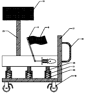
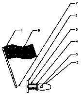
[0023] see Figures 1 to 3 , in an embodiment of the present invention, a warning device for electric power engineering, including a base 1, a fixed warning component and a movable warning component are arranged on the base 1, and the specific type of the fixed warning component is not limited. In this embodiment, Preferably, the fixed warning device includes a support column 23 and a second warning column 10, the second warning column 10 is fixedly installed on the top of the support column 23, and the bottom end of the support column 23 is welded on the base 1; the specific type of the movable warning assembly is not added. Restrictions, in this embodiment, preferably, the active warning assembly includes a cam 2, a motor 3, a reset member 5 of the movable plate 4, a fixed plate 6, a movable rod 7 and a support rod 8, and the motor 3 is fixedly installed inside the base 1 and the output terminal Drive and connect the cam 2, the movable plate 4 is connected with the cam 2, on...
Embodiment 2
[0031] see Figure 4 Considering that the height of the second warning bar 10 needs to be adjusted, this embodiment is further improved on the basis of Embodiment 1. The improvement is that: the support column 23 includes an externally threaded sleeve rod 11 and an internally threaded sleeve 12. The upper end of the threaded sleeve rod 11 is connected with the second warning bar 10, and the lower end is threadedly nested in the internally threaded sleeve 12, and the lower end of the internally threaded sleeve 12 is rotatably installed in the base 1, and the second helical gear 14 is fixedly installed on the periphery. The second helical gear 14 is engaged with the first helical gear 13, and the first helical gear 13 is fixedly installed on the rotating shaft 15. One end of the rotating shaft 15 extends to the outside of the base 1 and is connected with a rotating handle 16. The rotating handle 16 is covered with an anti-skid set. By turning the rotating handle 16, the first h...
PUM
 Abstract
Description
Claims
Application Information
 - R&D Engineer
- R&D Manager
- IP Professional
- Industry Leading Data Capabilities
- Powerful AI technology
- Patent DNA Extraction
Browse by: Latest US Patents, China's latest patents, Technical Efficacy Thesaurus, Application Domain, Technology Topic, Popular Technical Reports.
© 2024 PatSnap. All rights reserved.Legal|Privacy policy|Modern Slavery Act Transparency Statement|Sitemap|About US| Contact US: help@patsnap.com


