Cable laying vehicle

A cable laying and cable technology, which is applied to cable laying equipment, earthmoving machines/shovels, construction, etc., can solve the problems of low construction work efficiency, high energy consumption, high labor intensity, etc., and achieve good laying effect.

Inactive Publication Date: 2020-04-10
衢州柯城幕布电子有限公司
View PDF0 Cites 1 Cited by
  • Summary
  • Abstract
  • Description
  • Claims
  • Application Information

AI Technical Summary

Problems solved by technology

[0002] There is basically no special mechanical equipment for cable laying work. From the existing laying work, it can be seen that the existing construction work efficiency is low, the labor intensity is relatively high, and the energy consumption is relatively large. However, some cables need to be laid underground. The existing mechanical equipment cannot quickly and conveniently lay cables

Method used


Image

  • Cable laying vehicle
  • Cable laying vehicle
  • Cable laying vehicle

Examples


Embodiment Construction

[0017] Combine below Figure 1-6 The present invention is described in detail, and for convenience of description, the orientations mentioned below are now stipulated as follows: figure 1 The up, down, left, right, front and back directions of the projection relationship itself are the same.

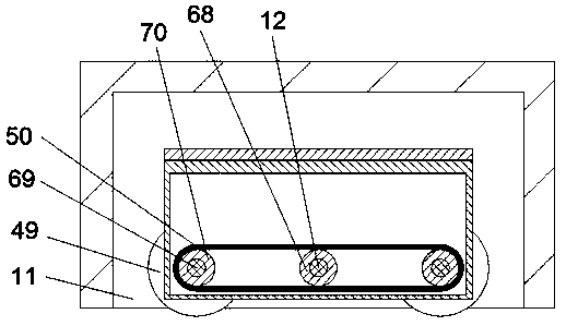
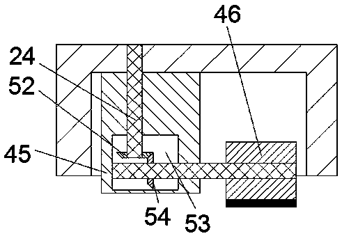
[0018] refer to Figure 1-6 , according to an embodiment of the present invention, a cable laying vehicle includes a casing 10, a driving chamber 33 is provided in the casing 10, a lifting mechanism 65 is arranged in the driving chamber 33, and the lifting mechanism 65 includes the The lifting motor 64 is fixedly connected to the rear end wall of the driving chamber 33. The casing 10 is provided with two rotating chambers 61. A driving shaft 19, the lower end of the driving shaft 19 is fixedly connected with a spiral bevel gear 63, the upper end of the driving shaft 19 is fixedly connected with the first transmission pulley 17, and the front and rear walls of the rotating chamber 61 ar...


PUM


Abstract

The invention discloses a cable laying vehicle which comprises a shell. Two moving wheels are arranged in the shell, a traction cavity is arranged in the shell, a traction shaft is rotationally connected to the front end wall of the traction cavity and wound by multiple layers of cables, a groove digging mechanism is arranged in the shell and comprises digging teeth arranged in the shell, the digging teeth can be rotated so as to dig grooves, a laying cavity is arranged in the shell and is in sliding connection with a fixing block, a lifting block is fixedly connected to the lower end of the fixing block, a reversing cavity is arranged in the lifting block, the rear end wall of the reversing cavity is rotationally connected with a laying shaft with the front end located in the laying cavity, a laying wheel is fixedly connected to the front end of the laying shaft, the rear end of the laying shaft is fixedly connected with a cable, one end of the cable is located at the lower end of thelaying wheel, a burying mechanism is arranged in the shell and comprises a burying wheel, and the burying wheel can be rotated to fill the grooves dug by the digging teeth.

Description

technical field [0001] The invention relates to the technical field of cables, in particular to a cable laying vehicle. Background technique [0002] There is basically no special mechanical equipment for cable laying work. From the existing laying work, it can be seen that the existing construction work efficiency is low, the labor intensity is relatively high, and the energy consumption is relatively large. However, some cables need to be laid underground. The existing mechanical equipment cannot quickly and conveniently lay cables. Contents of the invention [0003] The object of the present invention is to provide a cable laying vehicle for overcoming the above-mentioned defects in the prior art. [0004] A cable laying vehicle according to the present invention comprises a casing, a driving chamber is arranged in the casing, a lifting mechanism is arranged in the driving chamber, and the lifting mechanism includes a lifting mechanism fixedly connected to the rear end...

Claims


Application Information

Patent Timeline
IPC IPC(8): E02F5/10H02G1/06
CPCE02F5/109H02G1/06
Inventor 不公告发明人
Owner 衢州柯城幕布电子有限公司
Why Eureka
Try Eureka