
Laying structure of water supply and drainage engineering pipeline

A technology of water supply and drainage engineering, applied in the field of laying structure of pipelines in water supply and drainage engineering, which can solve the problems of inconvenient removal of fixed equipment, easy movement of pipelines, and reduced work efficiency, so as to achieve good laying effect, good practicability, and improve work efficiency Effect

Inactive Publication Date: 2022-05-17
任萍萍 +5
View PDF0 Cites 0 Cited by
  • Summary
  • Abstract
  • Description
  • Claims
  • Application Information

AI Technical Summary

Problems solved by technology

[0004] 1. When the laying structure of the existing water supply and drainage engineering pipelines is used, the pipeline needs to be moved to the ground and fixed, and when fixed, the pipeline is easy to move, reducing work efficiency;
[0005] 2. When the laying structure of the existing water supply and drainage engineering pipeline is in use, since the pipeline is located underground, after the pipeline is fixed, it is not convenient to take out the fixed equipment, which increases the cost

Method used


Image

  • Laying structure of water supply and drainage engineering pipeline
  • Laying structure of water supply and drainage engineering pipeline
  • Laying structure of water supply and drainage engineering pipeline

Examples


Embodiment Construction

[0021] The present invention will be further described below in conjunction with the accompanying drawings, but the protection scope of the present invention is not limited to the following description.

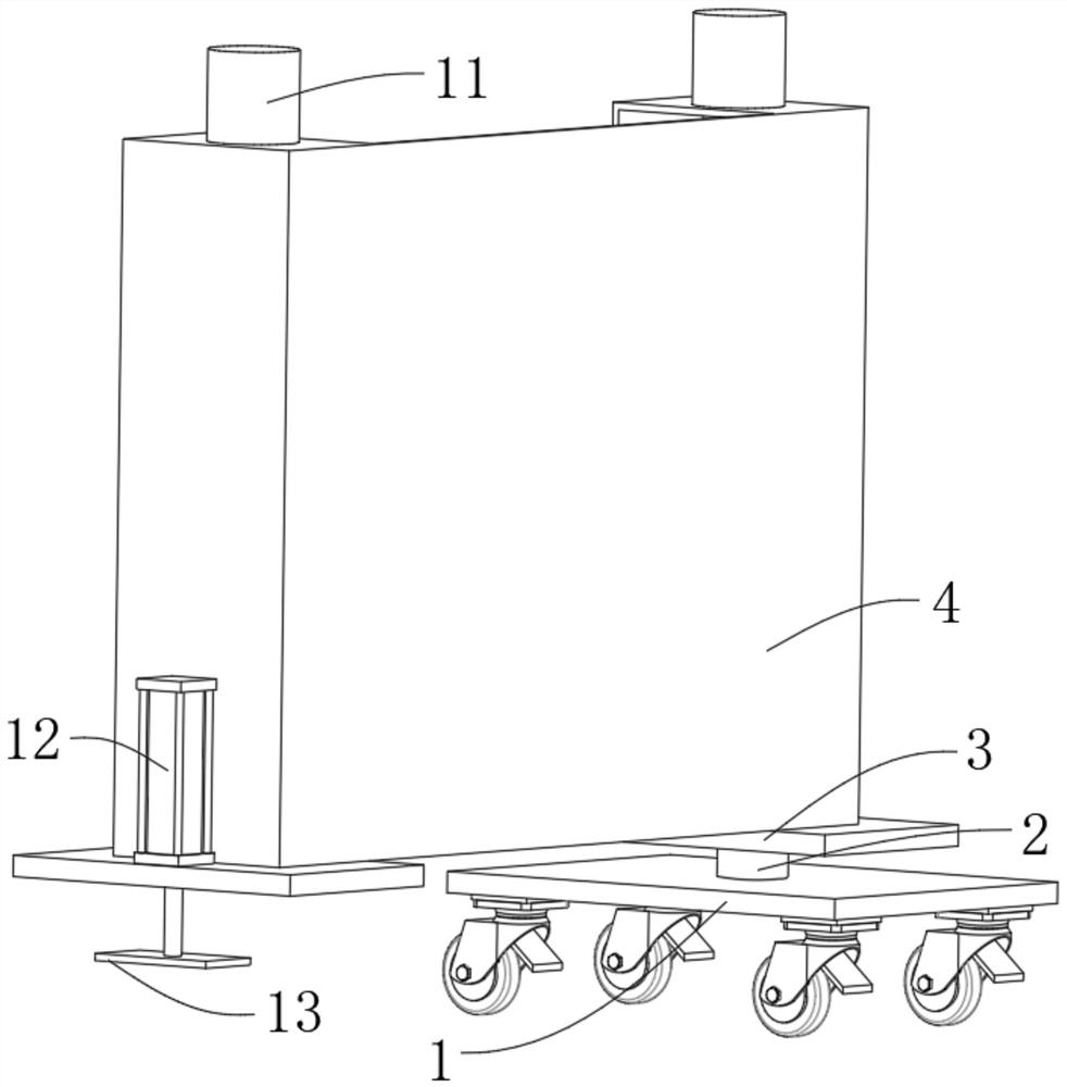
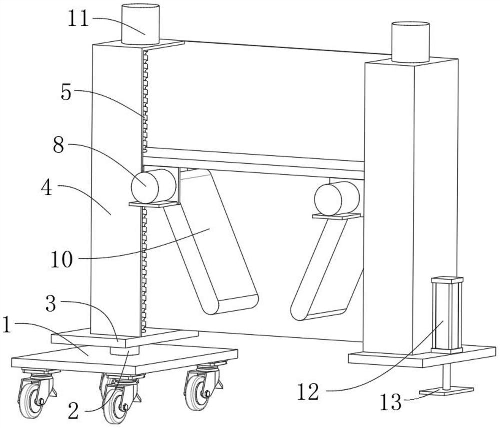
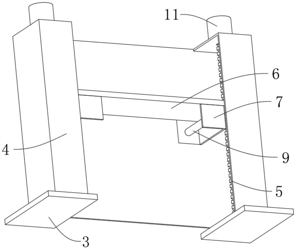
[0022] Such as Figure 1-3 As shown, a laying structure of water supply and drainage engineering pipelines, which includes a base 1, the top of the base 1 is movably connected with a support shaft 2, the top of the support shaft 2 is fixedly connected with a bottom plate 3, and the top of the bottom plate 3 is fixedly connected with a support frame 4 , the inside of the support frame 4 is movably connected with a screw mandrel 5, and the outer surface of the screw mandrel 5 is movably connected with a connecting plate 6, and the connecting plate 6 is movably connected to one side of the support frame 4;

[0023] The bottom of the connecting plate 6 is fixedly connected with a positioning plate 7, one side of the positioning plate 7 is fixedly connected with a first motor 8, t...


PUM


Abstract

The invention relates to the technical field of water supply and drainage engineering equipment, in particular to a water supply and drainage engineering pipeline laying structure which comprises a base, the top of the base is movably connected with a supporting shaft, the top of the supporting shaft is fixedly connected with a bottom plate, and the top of the bottom plate is fixedly connected with a supporting frame. The device has the advantages that the connecting plate is arranged, and the positioning plates are fixedly connected to the two ends of the bottom of the connecting plate, when the device is used, the pipeline is moved to the ground, the supporting frame is moved to the top of the pipeline, a second motor is started, a lead screw rotates in the connecting plate, and the connecting plate moves downwards on the supporting frame till a clamping plate moves to the position of the pipeline; the two clamping plates are located on the two sides of the pipeline correspondingly, at the moment, the first motors are started, the rotating shafts rotate, the clamping plates are driven to rotate, the clamping plates make contact with the pipeline, then the pipeline is fixed, in the pipeline laying process, movement of the pipeline is reduced, the laying effect is good, and the working efficiency is improved.

Description

technical field [0001] The invention relates to the technical field of water supply and drainage engineering equipment, in particular to a laying structure of water supply and drainage engineering pipelines. Background technique [0002] Water supply and drainage projects generally refer to urban water supply systems and drainage systems. The water supply and drainage pipe network is mainly used to realize the supply and discharge of urban use. Therefore, water supply and drainage pipes are commonly used components, and the pipes are usually installed underground to reduce space. Occupied, laying structures are required for installation. [0003] The shortcoming of the laying structure of existing water supply and drainage engineering pipeline is: [0004] 1. When the laying structure of the existing water supply and drainage engineering pipelines is used, the pipeline needs to be moved to the ground and fixed, and when fixed, the pipeline is easy to move, reducing work eff...

Claims


Application Information

Patent Timeline
IPC IPC(8): F16L1/06F16L1/028
CPCF16L1/06F16L1/028
Inventor 任萍萍魏鸾霄张昊辉王磊段正浩李旭
Owner 任萍萍
Learn More