
A detection and calculation method for the friction and wear boundary of the tooth flank of a high-feed milling cutter

A technology of friction and wear and boundary detection, which is applied in the direction of measuring/indicating equipment, metal processing equipment, metal processing machinery parts, etc., can solve the problem that the change characteristics of the cumulative friction and wear boundary cannot be known The formation of the cumulative friction and wear boundary of the cutter tooth flank Process and other problems, to solve the problem of thermal coupling field dissipation, solve the large error of evaluation, and ensure the effect of accuracy

Active Publication Date: 2021-07-16
HARBIN UNIV OF SCI & TECH
View PDF0 Cites 0 Cited by
  • Summary
  • Abstract
  • Description
  • Claims
  • Application Information

AI Technical Summary

Problems solved by technology

[0005] The present invention aims at the defects that the change characteristics of the cumulative friction and wear boundary cannot be completely described and the formation process of the cumulative friction and wear boundary of the cutter tooth flank cannot be known when the existing milling cutter flank is detected. The present invention provides a high-efficiency The detection and calculation method of the flank friction and wear boundary of the feed milling cutter can completely describe the change characteristics of the cumulative friction and wear boundary of the flank of the cutter, and reveal the formation process of the cumulative friction and wear boundary of the flank of the cutter

Method used


Image

  • A detection and calculation method for the friction and wear boundary of the tooth flank of a high-feed milling cutter
  • A detection and calculation method for the friction and wear boundary of the tooth flank of a high-feed milling cutter
  • A detection and calculation method for the friction and wear boundary of the tooth flank of a high-feed milling cutter

Examples


Embodiment 1

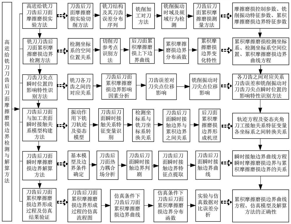
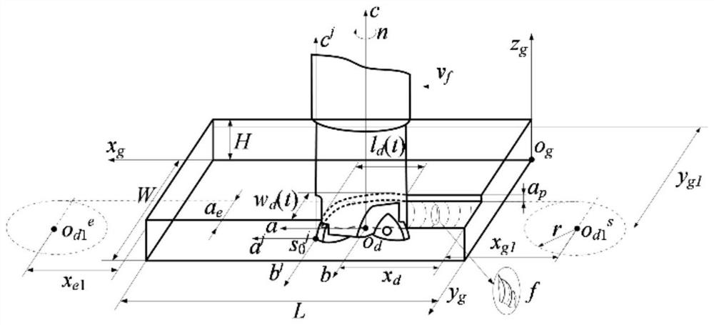
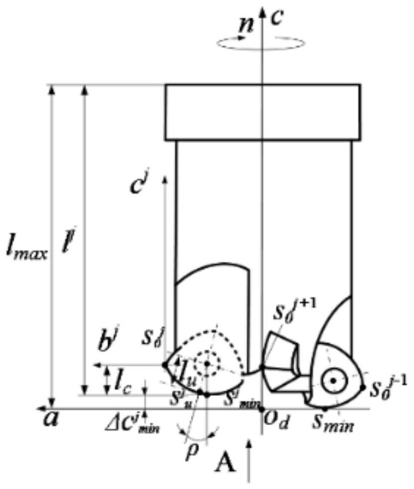
[0099] to combine figure 1 - Fig. 32 illustrates this embodiment. In this embodiment, a high-feed milling cutter tooth flank friction and wear boundary detection and solution method involved in this embodiment includes the following steps:

[0100]Step 1. High-feed milling cutter tooth flank friction and wear test method: multiple high-feed milling cutters with the same structure are used to perform milling experiments with different cutting strokes. Extract the geometric structure parameters of the workpiece and the machined surface, and establish the workpiece coordinate system; extract the structural characteristic variables of the milling cutter, and establish the milling cutter coordinate system; extract the characteristic variables of the cutter tooth structure, establish the cutter tooth coordinate system and the cutter tooth error distribution sequence; use the experiment to obtain the vibration Characteristic parameters and friction and wear samples of cutter tooth fl...


PUM


Abstract

A high-feed milling cutter tooth flank friction and wear boundary detection and calculation method belongs to the field of milling cutter tooth flank wear calculation methods, and the invention can completely describe the change characteristics of the cutter tooth flank friction and wear boundary , to reveal the formation process of the friction and wear boundary on the flank of the cutter tooth. In the present invention, a plurality of high-feed milling cutters with the same structure are used to carry out milling experiments with different cutting strokes respectively; a method for detecting the friction and wear boundary of the cutter tooth flank is proposed, and the change of the cumulative friction and wear boundary of the cutter tooth flank is revealed Characteristics; construct the instantaneous contact relationship model between the cutter tooth flank and the machined surface under the action of cutter tooth error and milling vibration, propose the instantaneous friction and wear boundary criterion of the cutter tooth flank, and obtain the instantaneous friction and wear boundary of the cutter tooth flank; The similarity of the coefficients of the experimental and simulation curve equations of the tooth friction and wear boundary verifies the correctness of the above model and method. The invention is mainly used for the detection and calculation of the friction and wear boundary of the cutter tooth flank of the milling cutter.

Description

technical field [0001] The invention belongs to the field of calculation methods for flank wear of high-feed milling cutters, and in particular relates to a method for detecting and calculating the friction and wear boundary of flanks of high-feed milling cutters. Background technique [0002] The change characteristics of the wear boundary of the flank of the milling cutter is an important parameter to evaluate the service life of the milling cutter. The measurement and calculation results of the friction and wear boundary directly affect the evaluation of the remaining service life of the milling cutter and the design of the milling process plan. High-feed milling cutter is a typical high-efficiency milling tool. During the intermittent cutting process, affected by factors such as cutter tooth error and milling vibration, the contact relationship between the cutter tooth flank and the workpiece processing surface changes frequently, resulting in The formation process of th...

Claims


Application Information

Patent Timeline
Patent Type & Authority Patents(China)
IPC IPC(8): B23Q17/09
CPCB23Q17/0957B23Q17/0971B23Q17/099
Inventor 姜彬王强赵培轶丁旺
Owner HARBIN UNIV OF SCI & TECH
Learn More