Pay-off equipment for power cable laying

A technology of power cables and cables, applied in the field of pay-off equipment, can solve the problems of low pay-off speed, slow pay-off speed, and inconvenient pay-off frame, etc., and achieve the effect of smooth pay-off, high efficiency and simple structure

Inactive Publication Date: 2020-04-14
魏洋洋
View PDF1 Cites 2 Cited by
  • Summary
  • Abstract
  • Description
  • Claims
  • Application Information

AI Technical Summary

Problems solved by technology

[0003] The power cable needs to use the pay-off frame during the laying process. The traditional pay-off frame is not convenient to use, and the pay-off speed is relatively low.
Chinese patent (authorized announcement number: CN208828986U) discloses a cable pay-off frame and a cable cutting device. Although the device can stop at any time during the pay-off process and can easily realize the cutting operation, in actual use The device has a relatively slow pay-off speed

Method used


Image

  • Pay-off equipment for power cable laying
  • Pay-off equipment for power cable laying
  • Pay-off equipment for power cable laying

Examples


Embodiment 1

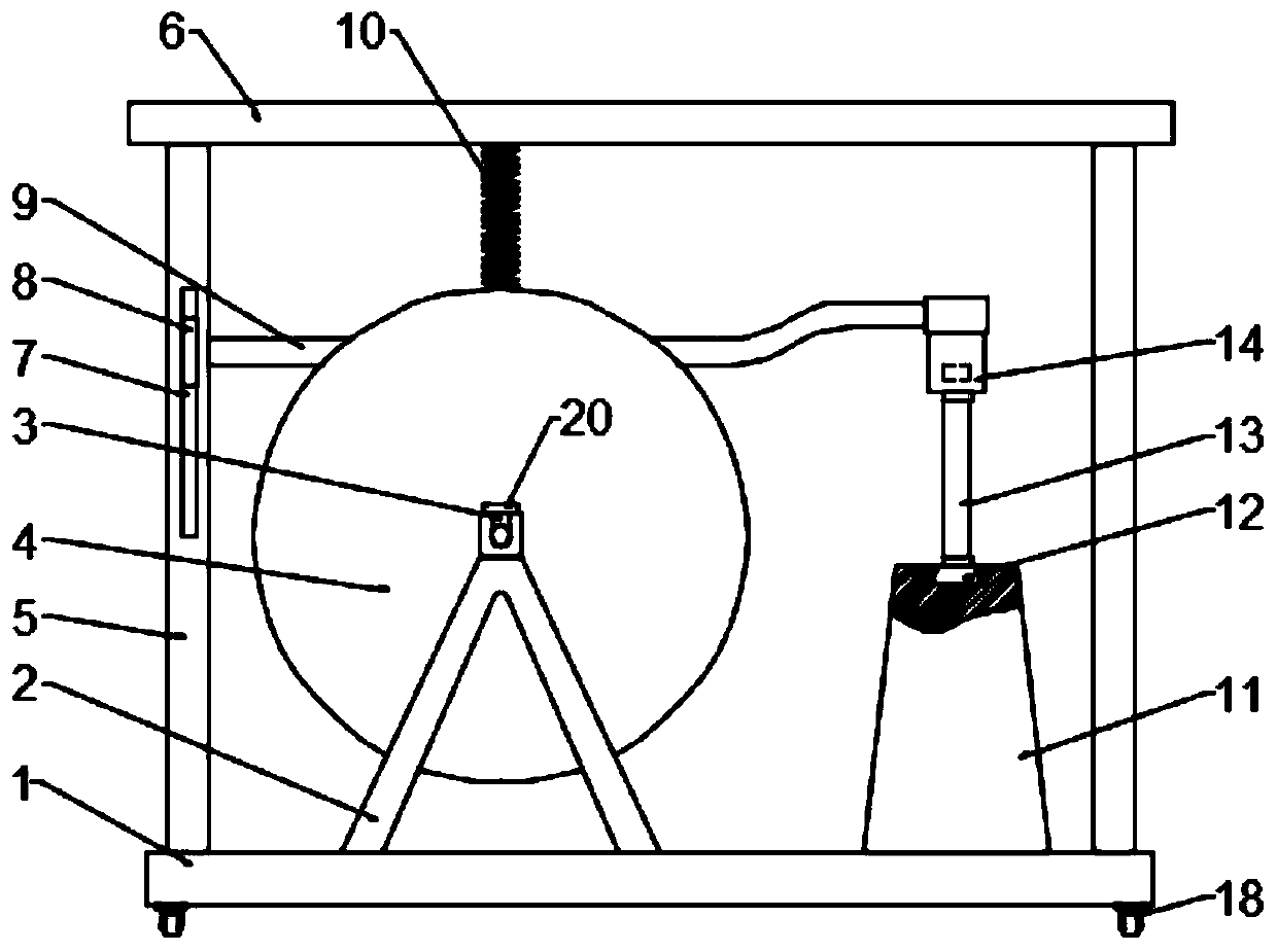
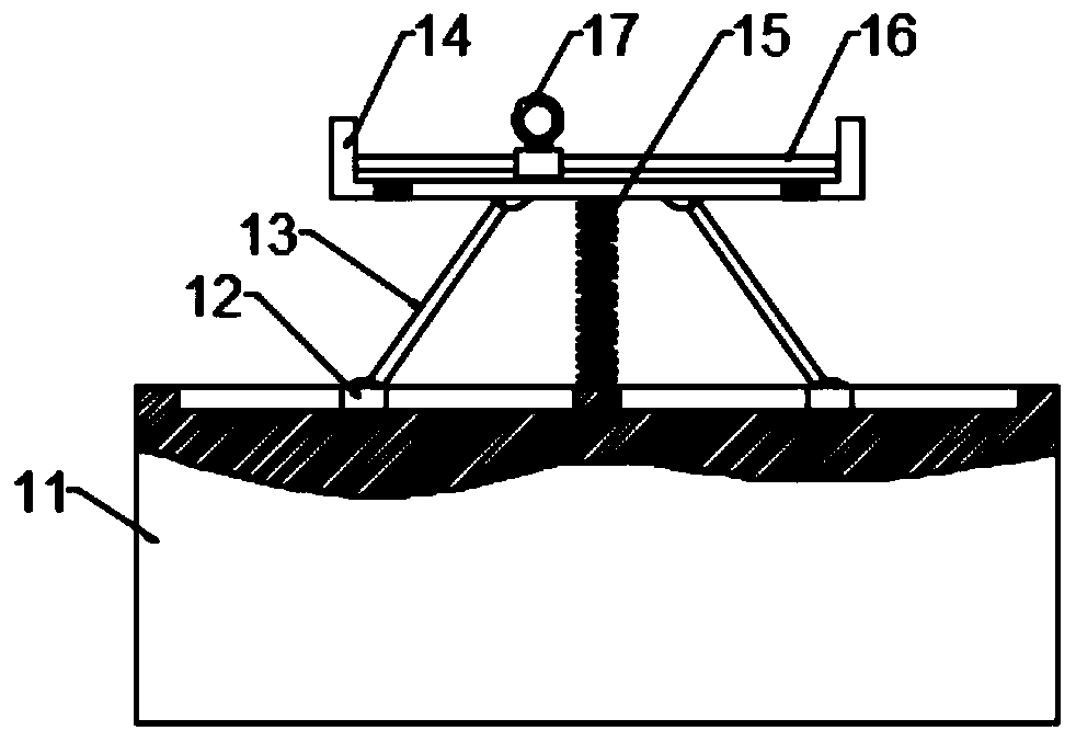
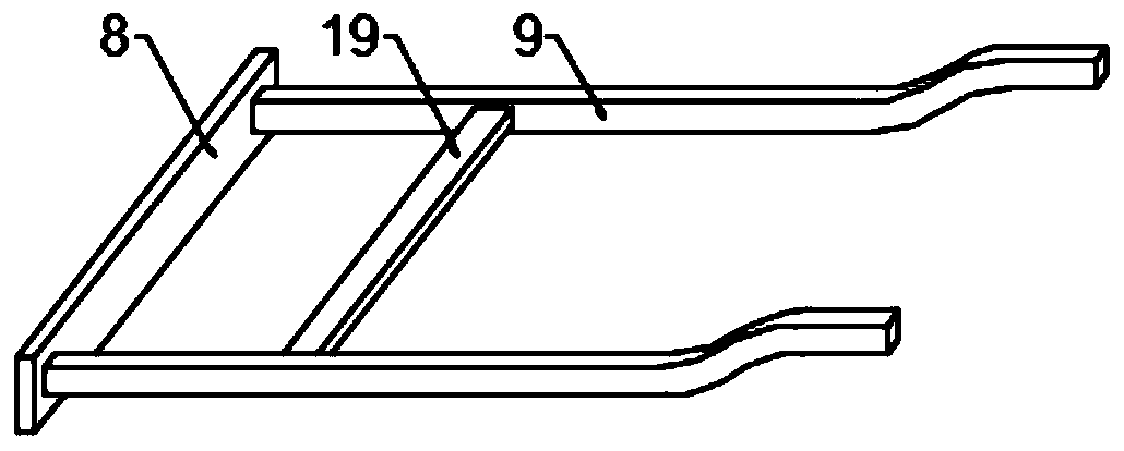
[0022] Example 1: Please refer to Figure 1-3 , a pay-off device for laying electric cables, comprising a fixed bottom plate 1, a bobbin connecting bracket 2 is fixedly connected to the upper left side of the fixed bottom plate 1, a groove 3 is opened on the top of the bobbin connecting bracket 2, and a cable bobbin is placed on the inner side of the groove 3 to rotate 4. The left and right sides of the fixed bottom plate 1 are fixedly connected with uprights 5 symmetrically, the top of the uprights 5 is fixedly connected with the upper beam 6, and the left side upright 5 is provided with a limit chute 7, and the inside of the limit chute 7 is slidingly connected with a limit Skateboard 8, the right side of limit slide plate 8 is symmetrically fixedly connected with adjusting rod 9 front and rear, and adjusting rod 9 cooperates with the cable on the cable spool 4, and is fixedly connected with first spring 10 on the upper beam 6, and the lower end of first spring 10 is connecte...

Embodiment 2

[0029] Example 2: Please refer to Figure 1-3 , in this embodiment, it includes a fixed bottom plate 1, and the upper left side of the fixed bottom plate 1 is fixedly connected with a bobbin connecting bracket 2, and the top of the bobbin connecting bracket 2 is provided with a groove 3, and the inner side of the groove 3 is rotated to place a cable bobbin 4. The top of the slot 3 is movably connected with buckles 20, and the buckles 20 are used for clamping the cable spool 4 to prevent the cable spool 4 from breaking away from the groove 3 during the unwinding process. The top of the fixed base plate 1 is symmetrically fixedly connected with uprights 5 and uprights. 5. The upper beam 6 is fixedly connected to the top, and the limit chute 7 is provided on the left column 5, and the limit slide 8 is slidably connected to the limit slide 8, and the right side of the limit slide 8 is symmetrically fixedly connected with an adjustment rod 9 , the adjusting rod 9 cooperates with th...

Embodiment 3

[0033] Example 3: Please refer to Figure 4 , in the present embodiment, it includes a fixed bottom plate 1, the upper left side of the fixed bottom plate 1 is fixedly connected with a bobbin connection bracket 2, the top of the bobbin connection bracket 2 is provided with a groove 3, and the inner side of the groove 3 is rotated to place a cable bobbin 4, the fixed The left and right sides of the bottom plate 1 are fixedly connected with uprights 5 symmetrically, the top of the uprights 5 is fixedly connected with an upper beam 6, and a limit chute 7 is provided on the left side upright 5, and a limit slide 8 is slidably connected in the limit chute 7, and the limit The right side of the slide plate 8 is symmetrically fixedly connected with an adjusting rod 9 front and rear, the adjusting rod 9 cooperates with the cable on the cable spool 4, the upper beam 6 is fixedly connected with a first spring 10, and the lower end of the first spring 10 is fixedly connected with the adju...


PUM


Abstract

The invention discloses pay-off equipment for power cable laying, and relates to pay-off equipment. The pay-off equipment comprises fixed bottom plate, the left side above the fixed bottom plate is fixedly connected with a bobbin connecting bracket; a groove is formed in the top of the bobbin connecting bracket; a cable shaft is rotationally placed on the inner side of the groove; stand columns are fixedly connected to the upper portion of the fixed bottom plate in a bilateral symmetry mode. An upper beam is fixedly connected to the top of the stand column, a limiting sliding groove is formedin the left stand column, a limiting sliding plate is slidably connected into the limiting sliding groove, adjusting rods are fixedly connected to the right side of the limiting sliding plate in a front-back symmetrical mode and matched with cables on the cable shaft, and a first spring is fixedly connected to the upper beam. The cable pay-off equipment is simple in structure and convenient to use, the adjusting rods are pressed through the first spring, so that a limiting ring on a sliding support is always kept at the same height as the cable through the adjusting rods in the pay-off process, the situation that the cable is wound in the pay-off process is avoided, and the whole equipment is smooth in pay-off and high in efficiency.

Description

technical field [0001] The invention relates to a pay-off device, in particular to a pay-off device for laying electric cables. Background technique [0002] Wires and cables play a very important role in the infrastructure construction of our country. With the continuous development of our country, for the power cable industry, the traditional industry model can no longer adapt to the development of the currency field in response to the ever-changing market and demand. Therefore, for many enterprises, the transformation of the industry is urgent. [0003] The power cable laying process needs to use the pay-off rack, the traditional pay-off rack is not convenient to use, and the pay-off speed is relatively low. Chinese patent (authorized announcement number: CN208828986U) discloses a cable pay-off frame and a cable cutting device. Although the device can stop at any time during the pay-off process and can easily realize the cutting operation, in actual use The payout speed...

Claims


Application Information

Patent Timeline
Patent Type & Authority Applications(China)
IPC IPC(8): B65H49/30B65H57/06
CPCB65H49/30B65H57/06B65H2701/34
Inventor 魏洋洋
Owner 魏洋洋
Why Eureka
Try Eureka