An ecological guardrail for urban roads

A road and ecological technology, applied in the field of urban ecological construction equipment, can solve the problems of no ecological guardrail, plant drought, plant watering, etc., and achieve the effect of saving time and energy

Active Publication Date: 2021-04-30
安徽大通建设工程有限公司
View PDF7 Cites 0 Cited by
  • Summary
  • Abstract
  • Description
  • Claims
  • Application Information

AI Technical Summary

Problems solved by technology

[0003] However, the existing ecological guardrails do not have the function of automatically watering the plants at high temperatures, which requires manual watering or the use of equipment such as sprinklers to water the plants, and multiple waterings are required. It has brought great inconvenience to the staff, and, once the watering is not on time, the plants are likely to die of drought due to high temperature

Method used


Image

  • An ecological guardrail for urban roads
  • An ecological guardrail for urban roads
  • An ecological guardrail for urban roads

Examples


Embodiment 1

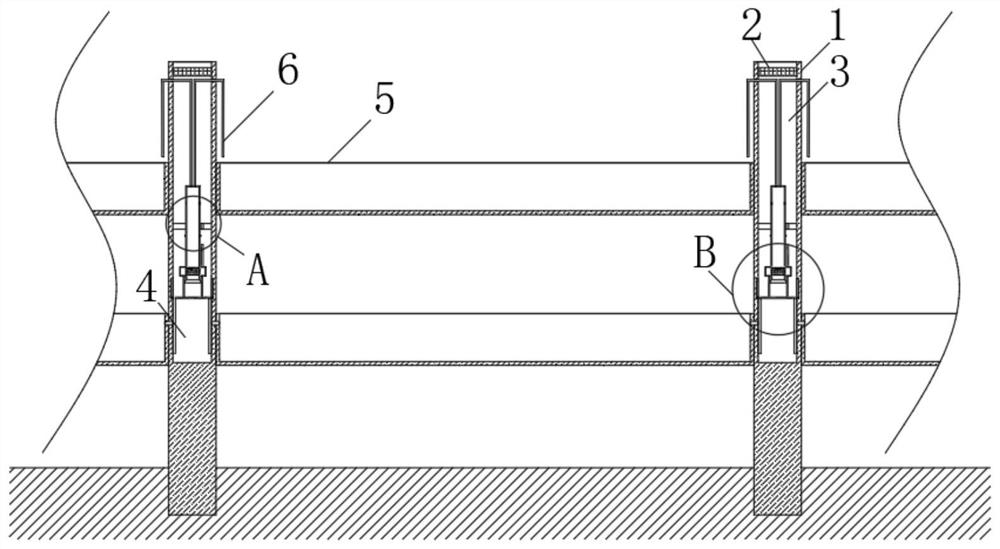
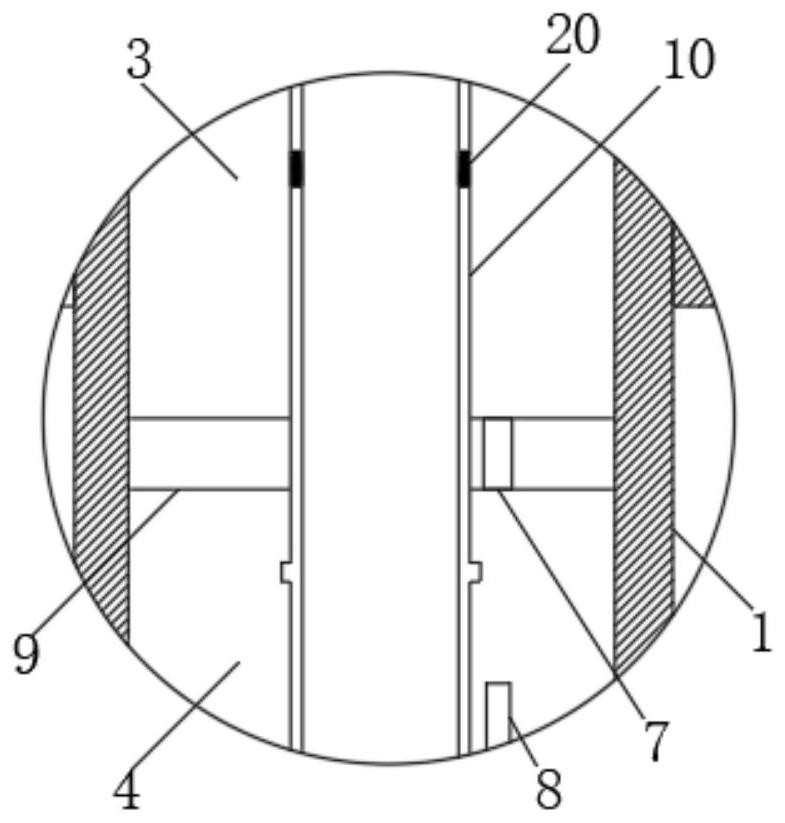
[0022] refer to Figure 1-5 , an ecological guardrail for urban roads, comprising a plurality of road piles 1 arranged at equal intervals on both sides of the road, two adjacent side walls of two road piles 1 opposite to each other are provided with two planting boxes 5, and the upper wall of the road pile 1 is provided with There is a cylindrical tank, and the inner wall of the cylindrical tank near the middle is provided with a partition 9. The partition 9 separates the cylindrical tank into a water storage tank 3 at the upper end and a control tank 4 at the lower end. The water in the water storage tank 3 can be collected by collecting Rainwater or artificial water is added for replenishment.

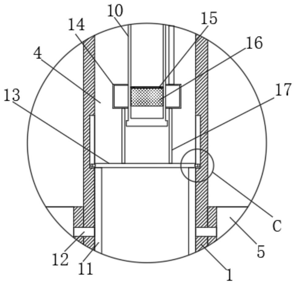
[0023] The water storage tank 3 and the control tank 4 are jointly provided with a water supply mechanism. The water supply mechanism includes a water injection cylinder 10 fixedly inserted in the middle of the partition 9. The side wall of the water injection cylinder 10 located at ...

Embodiment 2

[0028] refer to Figure 1-6 In this embodiment, on the basis of Embodiment 1, a municipal water tank 21 higher than road pile 1 is set beside the road, and the water outlet of the municipal water tank 21 is connected with a main pipe 22, and the main pipe 22 is respectively connected to the water storage tank 3 through a plurality of branch pipes 23. Each branch pipe 23 is equipped with a branch valve 24, and the end of the main pipe 22 close to the municipal water tank 21 is provided with a main valve 25, and the staff can realize all road piles 1 or a single road by switching the main valve 25 or branch valve 24. Pile 1 supplies water.

[0029] Compared with Embodiment 1, this embodiment does not need to manually pour water into the water storage tank 3. When the water in the water storage tank 3 flows into the planting box 5, the water in the municipal water tank 21 will be under the action of gravity (the municipal water tank 21 and the road pile 1 have a height Poor) con...


PUM


Abstract

The invention discloses an ecological guardrail for urban roads, which comprises a plurality of road piles arranged at equal intervals on both sides of the road. A cylindrical tank is provided, and the inner wall near the middle part of the cylindrical tank is provided with a partition, and the partition board separates the cylindrical tank into a water storage tank at the upper end and a control tank at the lower end, and the inside of the water storage tank and the control tank A water supply mechanism is jointly provided, and the water supply mechanism includes a water injection cylinder fixedly inserted in the middle of the partition, and the side wall of the water injection cylinder at the lower end of the partition is provided with two limit rings, and the water injection cylinder is located at the lower end of the partition The sliding sleeve on the outer wall is provided with a heat-expandable floating block, and the heat-expandable floating block has an annular structure. The present invention can automatically supply and cut off the water to the plants in the planting box according to the temperature change, thus ensuring that the plants will not die due to the high-temperature environment drought, and saving a lot of time and energy for the staff.

Description

technical field [0001] The invention relates to the technical field of urban ecological construction equipment, in particular to an ecological guardrail for urban roads. Background technique [0002] With the continuous development of science and technology, our environment has been greatly harmed, and environmental problems have attracted more and more attention from the whole society. Some cities have also begun to build some public facilities that can protect the environment. For example, in cities Set up some ecological guardrails on both sides of the road. The ecological guardrails are to plant some green plants and flowers on the guardrails, which can not only play a beautiful role in the urban environment, but also make passers-by happy. At the same time, they can also use the photosynthesis of plants to purify the city air, protect the environment. [0003] However, the existing ecological guardrails do not have the function of automatically watering the plants at h...

Claims


Application Information

Patent Timeline
Patent Type & Authority Patents(China)
IPC IPC(8): E01F15/02E03B3/02E03B11/00A01G9/02A01G27/00
CPCA01G9/02A01G27/00E01F15/02E03B3/02E03B11/00Y02A20/108
Inventor 蔡路李玉枫
Owner 安徽大通建设工程有限公司
Why Eureka
Try Eureka