
Device and method for controlling plurality of LED power supplies in parallel connection with light-operated and dimming functions

A technology of LED power supply and control device, applied in the use of electrical components and semiconductor lamps, etc., can solve the problems of not being able to know the technical details and not revealing the main control module

Active Publication Date: 2020-04-14
SHENZHEN MESTER OPTOELECTRONICS TECH CO LTD
View PDF12 Cites 0 Cited by
  • Summary
  • Abstract
  • Description
  • Claims
  • Application Information

AI Technical Summary

Problems solved by technology

However, the technical solution of this patent does not disclose the specific control method of how the main control module determines the PWM signal to be output according to the illuminance value, and the specific technical details cannot be known.

Method used


Image

  • Device and method for controlling plurality of LED power supplies in parallel connection with light-operated and dimming functions
  • Device and method for controlling plurality of LED power supplies in parallel connection with light-operated and dimming functions
  • Device and method for controlling plurality of LED power supplies in parallel connection with light-operated and dimming functions

Examples


Embodiment Construction

[0053] Explanation: In this patent application document, if there are expressions similar to "first resistance" and "second resistance", it does not necessarily mean that "first resistance" must appear before "second resistance" in this article. Just to show that these are two different gauge resistors. Sometimes, in order to match the description of the circuit diagram, "the second resistor" may appear before the "first resistor" in the claims or specification.

[0054] In order to make the technical problems, technical solutions and beneficial effects to be solved by the present invention clearer, the present invention will be further described in detail below in conjunction with the accompanying drawings and embodiments. It should be understood that the specific embodiments described here are only used to explain the present invention, not to limit the present invention.

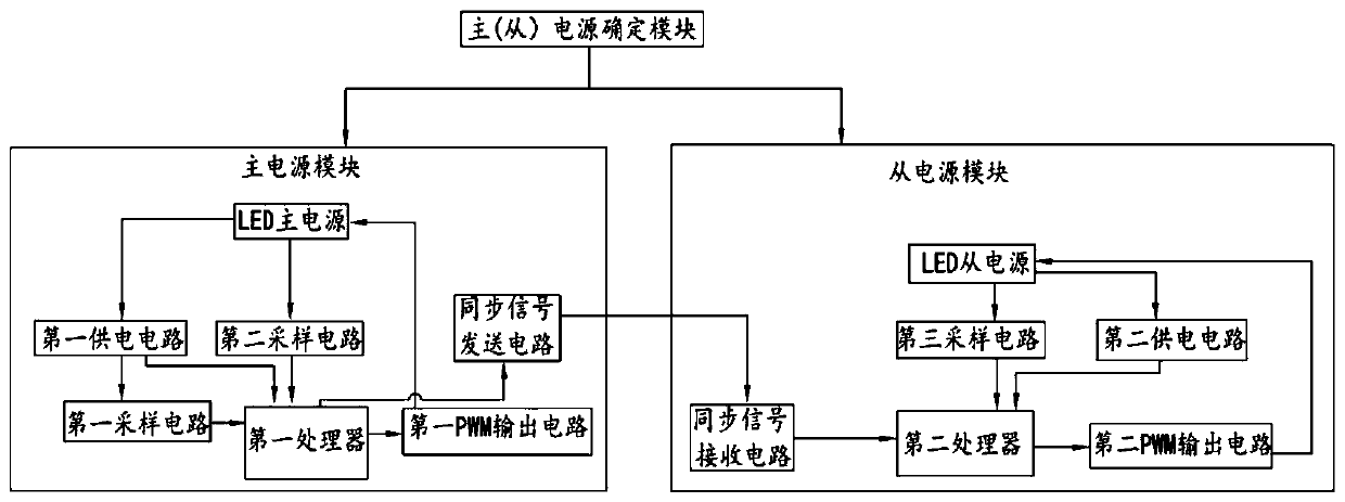
[0055] refer to figure 1 , the present invention discloses a control device with multiple LED power ...


PUM


Abstract

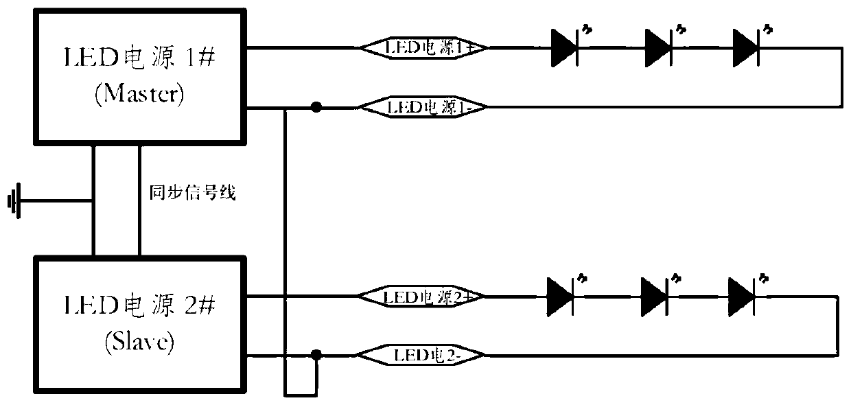
The invention discloses a device for controlling a plurality of LED power supplies in parallel connection with light-operated and dimming functions. The device comprises a master-slave power supply determination module, a master power supply module and a slave power supply module. The master-slave power supply determination module is used for setting the master power supply module and the slave power supply module according to a detection result of an environment state; and the master power supply module converts collected environment state detection information into a synchronizing signal, sends the synchronizing signal to a synchronizing signal receiving circuit through a synchronizing signal sending circuit, reads the synchronizing signal from the power supply module, and decides whether to turn on output and enable dimming or turn off the output and turn off a dimming function according to a reading result of the synchronizing signal. The invention further discloses a control method corresponding to the device. According to the device and the method, control precision is enhanced, overall control performance is improved, and cost is reduced.

Description

technical field [0001] The invention relates to the lighting field of LED lighting devices, in particular to a control device and a control method for parallel connection of multiple LED power supplies with light control and light adjustment functions. Background technique [0002] Patent 2017206477155 discloses an intelligent lighting control system, which directly converts light information into corresponding light digital values, and transmits the light intensity value to the main control module through I2C communication, and the main control module determines the PWM that should be output according to the illuminance value. (Pulse Width Modulation, Pulse Width Modulation) signal, and the LED drive output rated current under the control of the PWM signal, so that the LED lighting device has a corresponding brightness. This process is in an infinite loop. According to the light value obtained in real time, the brightness of the LED lighting fixture is adjusted in real time...

Claims


Application Information

Patent Timeline
Patent Type & Authority Applications(China)
IPC IPC(8): H05B45/14H05B45/325H05B45/34H05B45/3725H05B45/395
CPCY02B20/30
Inventor 马二华李秀飞林璐
Owner SHENZHEN MESTER OPTOELECTRONICS TECH CO LTD
Learn More