Clay numerical control milling clamping platform and clamping method

A CNC milling and platform technology, applied in the direction of clamping, positioning device, support, etc., can solve the problems of poor repeat positioning accuracy, waste of time, large human influence factors, etc., and achieve the effect of fast clamping and alignment

Active Publication Date: 2020-04-17
FAW JIEFANG AUTOMOTIVE CO
View PDF8 Cites 1 Cited by
  • Summary
  • Abstract
  • Description
  • Claims
  • Application Information

AI Technical Summary

Problems solved by technology

[0004] ①The process of model alignment is cumbersome, and the angle of the body needs to be adjusted continuously, wasting time
[0005] ②The accuracy of model alignment is poor, and it is too much affected by human factors
[0006] ③Repeated positioning accuracy is poor. When the model is processed for the second time, all previous alignment and clamping coordinate presets need to be done again, which is a waste of time and the accuracy is poor.
[0007] ④ Poor reliability. The model and the positioning column are fastened by the weight of the vehicle body. When processing a partial model or a split model, there will be a problem of insufficient fastening force
[0008] ⑤ Poor versatility. When this clamping is applied to cars, the universality problem is not obvious. When it is applied to trucks, because trucks are generally processed separately, it will involve different model parts for replacement. This clamping cannot be used universally for different models. piece

Method used


Image

  • Clay numerical control milling clamping platform and clamping method
  • Clay numerical control milling clamping platform and clamping method
  • Clay numerical control milling clamping platform and clamping method

Examples


Embodiment Construction

[0036] The technical solutions of the present invention will be further explained and illustrated in the form of specific embodiments in conjunction with the accompanying drawings.

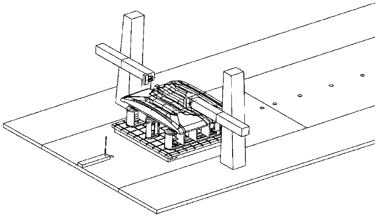
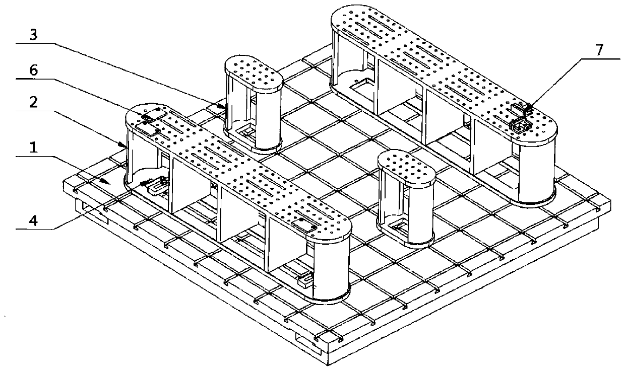
[0037] Such as figure 2 As shown, a clamping platform for oil sludge CNC milling, the platform includes a T-slot platform 1, a long stool 2, a short stool 3, a rotating shaft 4, a limit block 5, a fixed positioning block 6, a movable positioning block 7 and a fixed block 8;

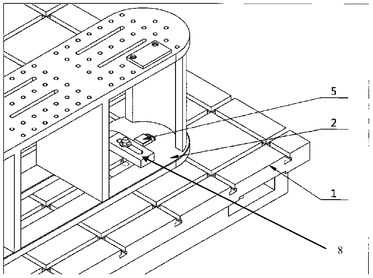
[0038] Wherein, said bench 2 is as Figure 5a ~ Figure 5d As shown, the upper and lower end faces are oblate, and the upper and lower end faces are fixed by several support columns; image 3 As shown, the center of one end of the flat circle is the center of rotation, and a mounting hole for the rotation shaft 4 is opened on the center of rotation of the lower end face, as shown in Figure 7a ~ Figure 7c As shown, the upper end of the rotating shaft 4 is installed in the mounting hole, and the lower end is installed at th...


PUM


Abstract

The invention discloses a clay numerical control milling clamping platform and a clamping method, and belongs to the technical field of automobile clay model machining. The platform is used for solving the problems that an existing clamping platform is troublesome in alignment, poor in universality, low in precision and the like. The clay numerical control milling clamping platform comprises a T-shaped groove platform, a long bench, a short bench, a rotating shaft, a limiting block, a fixed positioning block, a movable positioning block and a fixing block. The platform is designed aiming at clay milling and clamping, the advantages of T-shaped grooves are fully utilized, the positioning block and the movable positioning block are used for realizing quick clamping and alignment, coordinatecalibration is realized by utilizing the longitudinal and transverse T-shaped grooves, therefore coordinate presetting is not needed, and generalization is realized through cooperation of the long bench, the short bench and matrix holes.

Description

technical field [0001] The invention belongs to the technical field of automobile sludge model processing. Background technique [0002] The milling of the automobile clay model is generally carried out on the sludge milling machine, and the machine tool platform of the sludge milling machine is usually a smooth platform without positioning and fastening mechanisms. [0003] At present, the common practice in the industry is to position the model on the machine tool platform through the positioning column, and the positioning column is fastened on the machine tool platform by hand-mixing resin or structural glue. Before tightening, straightening and alignment and preset coordinates are performed with machine tool assistance. There are five disadvantages of this approach: [0004] ①The process of model alignment is cumbersome and requires constant adjustment of the body angle, wasting time. [0005] ②The accuracy of model alignment is poor, and it is too much affected by h...

Claims


Application Information

Patent Timeline
Patent Type & Authority Applications(China)
IPC IPC(8): B23Q3/06
CPCB23Q3/062
Inventor 丁路孙一卜显俊袁晓波杨大力张禹彬薛成瑞
Owner FAW JIEFANG AUTOMOTIVE CO
Why Eureka
Try Eureka