A clamping and processing method for multi-station inner wing parts

A multi-station and parts technology, applied in the direction of metal processing machinery parts, positioning devices, metal processing equipment, etc., can solve the problems of frequent clamping and replacement, consume huge manpower and material resources, and restrict the development of missile weapon manufacturing industry, etc., and achieve reduction The effect of production preparation time and artificial delay time, concentrated and continuous processing time, and shortened machine downtime

Active Publication Date: 2019-08-06
BEIJING XINGHANG MECHANICAL ELECTRICAL EQUIP
View PDF8 Cites 0 Cited by
  • Summary
  • Abstract
  • Description
  • Claims
  • Application Information

AI Technical Summary

Problems solved by technology

[0003] The inner wing parts are divided into rough and finish machining during the machining process. Both rough and finish machining include four-surface feature processing, frequent clamping and replacement, and repeated clamping positioning accuracy is difficult to guarantee
In the traditional processing of inner wing parts, the self-made positioning tool is used to position and clamp the part through the process chucks at both ends of the part, and the precision and reference transmission are guaranteed through the process pin hole and the high-precision pin hole on the part. The tooling interchangeability of various types of parts is poor, and the manufacture of different types of inner wings requires different special tooling. The design, manufacture, storage and management of this tooling require huge human and material resources and are not conducive to the development of new products and single-piece Small batch production; in addition, the part clamping and alignment process takes a long time
Seriously restricting the development of the missile weapon manufacturing industry

Method used


Image

  • A clamping and processing method for multi-station inner wing parts
  • A clamping and processing method for multi-station inner wing parts
  • A clamping and processing method for multi-station inner wing parts

Examples


Embodiment Construction

[0031] In order to make the purpose, content, and advantages of the present invention clearer, the specific implementation manners of the present invention will be further described in detail below in conjunction with the accompanying drawings and embodiments.

[0032] The present invention proposes a processing method for processing multi-type inner wing parts, which specifically includes the following steps:

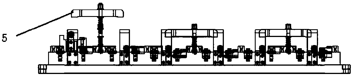
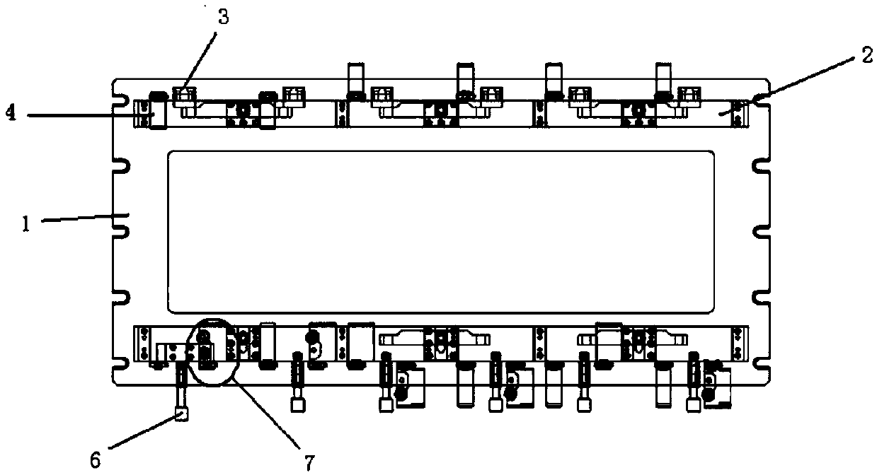
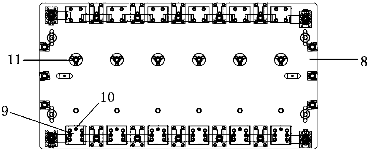
[0033] Step 1. First design three multi-station clamping fixtures for the processing of multi-model inner wing parts: 1. Rough machining fixture; 2. Finishing deep cavity fixture; 3. Finishing both side profile fixtures.

[0034] The rough machining fixture structure includes: a first base 1, a first positioning unit 2, a second positioning unit 3, a third positioning unit 4, a first pressing unit 5, a second pressing unit 6, and a third pressing unit 7 , the size of the first base 1 is determined according to the size of the XH-718 worktable of the machine tool used f...


PUM


Abstract

The invention relates to a multi-station clamping processing method for inner wing parts, and relates to the technical field of aircraft part processing and manufacturing. According to the processingmethod disclosed by the invention, a multi-station camping tool used for processing inner wing parts of various models is designed, local positioning units and local clamping units can be replaced while inner wings of different models are processed, each positioning unit passes through a high-precision pin hole in a high-precision datum plane, high-precision pin holes in parts and a high-precisionpin hole in a process chuck, so that quick clamping and aligning of parts is realized; multiple parts are simultaneously clamped and processed, so that downtime of a machine tool can be shortened toa greater extent, the rocessing efficiency is improved to a greater extent, inner wing parts of various models can be simultaneously clamped and processed, and aligning is convenient; and production preparation time and manual delay time can be effectively reduced after clamping is completed, so that the processing time is more intensive and continuous, and therefore, more and better choices are provided for production scheduling.

Description

technical field [0001] The invention relates to the technical field of aircraft parts processing and manufacturing, in particular to a multi-station clamping and processing method for inner wing parts. Background technique [0002] In aircraft products, inner wing parts are a very important part of the empennage structure. The structure of this type of parts is complex, with processing features on all four sides. The dimensional accuracy of each feature is required to be high, and there is no large plane for clamping; In addition, during the batch production of model products, the number of inner wing parts is huge. It is a difficult point in actual production to ensure reliable product quality and meet processing cycle requirements. [0003] The inner wing part is divided into rough and finish machining during the machining process. Both rough and finish machining include feature processing of four surfaces. The clamping and replacement are frequent, and the positioning ac...

Claims


Application Information

Patent Timeline
Patent Type & Authority Patents(China)
IPC IPC(8): B23Q3/06
CPCB23Q3/065
Inventor 申辰威刘军郝哲
Owner BEIJING XINGHANG MECHANICAL ELECTRICAL EQUIP
Why Eureka
Try Eureka